


You will need: flat-blade screwdriver, side cutters, punch, hammer, snap ring pliers.
1. Remove the front wheel drive assembly (see Removal and installation front wheel drives).
2. Clean the parts and inspect the drive:
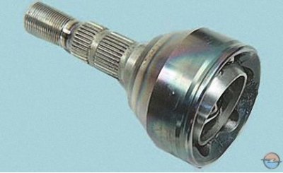
- the outer constant velocity joint should rotate with light force without jerking or jamming, radial and axial play. If any, replace the joint;
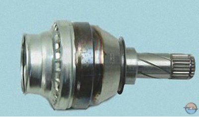
- the inner hinge should move in angular and axial directions with slight force, while jerking, jamming and radial play should not be felt. Otherwise, replace the inner hinge;
- the outer and inner hinge protective covers should not have any cracks or tears. Replace damaged covers;
- the wheel drive shaft must not be deformed. Replace the deformed shaft.
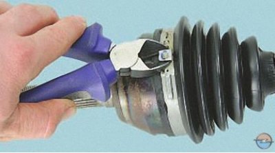
3. For replacement outer hinge or its cover disconnect with a screwdriver or cut the clamp with side cutters.
The clamps for fastening the protective covers of the constant velocity joints are single-use; replace them with new ones during assembly. As a rule, the clamps are included in the new joint kit.
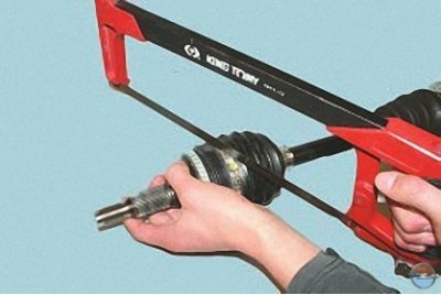
To make removal easier, the clamp can be cut with a hacksaw for metal. When cutting the clamp, be careful not to damage the edges of the groove for the cover on the hinge body.
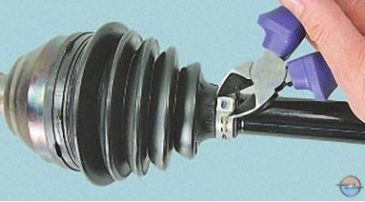
4. Remove the second cover mounting clamp in the same way.
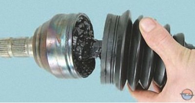
5. Slide the protective cover off the hinge housing and remove some of the grease from it.
6. Knock the joint cage off the shaft with a hammer through the punch, overcoming the force of the retaining ring.
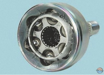
7. Remove the outer joint from the shaft splines.
Attention! Disassembling the outer hinge is not permitted.
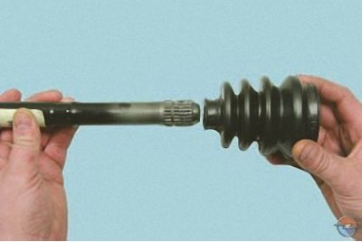
8. Remove the outer joint cover from the shaft.
Note: When installing the hinge, replace the protective cover with a new one. The cover is usually included with the new hinge.
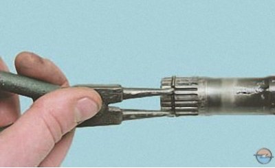
9. Use pliers to loosen the retaining ring and remove it from the shaft. Replace the retaining ring regardless of its condition.
10. Before installing the new outer joint, fill its cavity with 100 g of grease (if the joint was not lubricated by the manufacturer). First fill the hinge body, and then evenly distribute the remaining amount in the corrugations of the cover.
Note: If the lubricant recommended by the manufacturer is not available, you can use domestic molybdenum lubricant SHRUS-4.
11. Install the outer joint boot and the joint in the reverse order of removal. When installing the joint on the shaft, press the joint by hitting the joint shank with a hammer through a soft metal punch until the joint collar is secured with a retaining ring.
Caution: Before securing the hinge cover with a large clamp, pull back the edge of the cover with a screwdriver to equalize the air pressure inside and outside the cover.
12. For replacement internal hinge of the Lebro type and its cover remove the clamps securing the hinge boot to its housing and to the shaft in the same way as you did when removing the outer hinge.
[The article was published on the website OPELBOOK.ru]
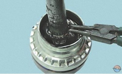
13. Spread the retaining ring tabs, while simultaneously using the punch to move the joint sleeve along the shaft splines…
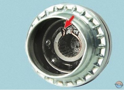
Note: This is how the retaining ring is located in the hinge cage (for clarity, shown on a removed hinge).
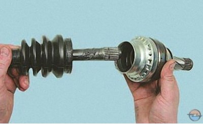
14. …and remove the inner joint from the shaft.
Attention! Disassembling the outer joint is not permitted.
15. Remove the retaining ring from the groove in the cage.
Note: When assembling, replace the retaining ring with a new one. The ring is usually included with the new joint.
16. Install the inner joint boot and the joint in the reverse order of removal. When installing the joint on the shaft, press the joint by hammering the joint shank through a soft metal drift until the joint collar is secured with a locking ring.
17. Before assembly, fill the housing cavity and the inner hinge cover with approximately 150 g of grease: 100 g in the hinge and 50 g in the cover.
Note: If the lubricant recommended by the manufacturer is not available, you can use domestic molybdenum lubricant SHRUS-4.
18. Assemble the inner joint in the reverse order of disassembly.
19. For replacement internal hinge type tripod and its cover remove the clamps securing the hinge boot to its housing and to the shaft in the same way as you did when removing the outer hinge.
20. If you disassemble the hinge to replace the cover and intend to install the old hinge, mark it in any way (for example, with a center punch, a file or paint) relative position of the hinge housing and the drive shaft.
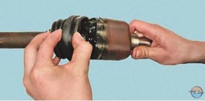
21. Slide the cover off the hinge housing…
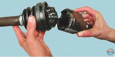
22. …and disconnect the housing from the drive.
23. Mark the position of the joint hub relative to the shaft (see item 20).
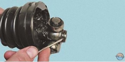
24. Using a screwdriver, pry up the retaining ring of the hinge hub…
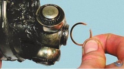
25. …remove the ring from the shaft groove.
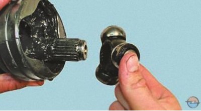
26. Remove the hub with rollers from the shaft splines…
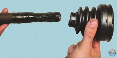
27. …and remove the protective cover from the shaft.
28. Wash all metal parts with kerosene until all old grease is removed.
29. Inspect the rollers, hub and inner cavity of the housing. Scoring, dents and corrosion are not allowed. The rollers should rotate on their bearings freely, without jamming. If faults are found, replace the joint assembly.
30. Install the joint cover on the shaft and secure it with a clamp.
31. Install the joint hub onto the shaft splines, aligning the marks made during disassembly, and secure it with a retaining ring.
32. Fill the cavity of the inner hinge with grease in an amount of about 100 g. First fill the hinge housing, and then evenly distribute the remaining amount in the corrugations of the cover.
Note: If the lubricant recommended by the manufacturer is not available, you can use domestic molybdenum lubricant SHRUS-4.
33. Install the hinge housing, aligning the marks made during disassembly.
34. Place the cover on the hinge body and secure it with a clamp.
Caution: Before securing the hinge cover with a large clamp, pull back the edge of the cover with a screwdriver to equalize the air pressure inside and outside the cover.
Visitor comments