


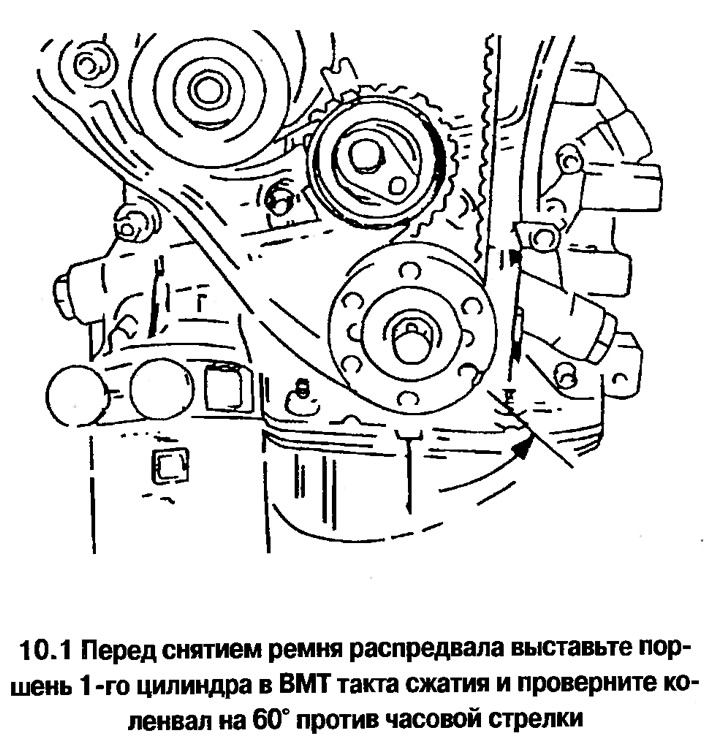
2. Remove the camshaft sprockets.
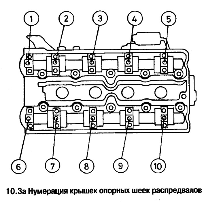
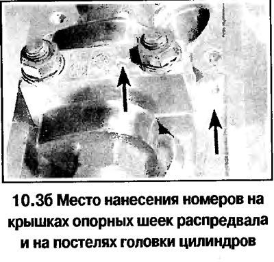
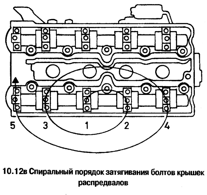
3. In the reverse order to that indicated for tightening (see photo below) unscrew the nuts of the intake camshaft bearing journal covers. Unscrew the nuts evenly and gradually, making 1 turn at a time, until the bolts can be unscrewed by hand. The intake camshaft covers are numbered from 1 to 5, the exhaust camshaft covers are numbered from 6 to 10 (see photo).
Article published on the website www.OPELBOOK.ru
Attention! Do not violate the order of unscrewing the bolts, otherwise the cover may crack due to uneven action of the valve springs. In case of cover breakage, the cylinder head should be replaced together with all covers. The bearing journal covers are processed together with the camshaft beds in the cylinder head and are not supplied separately as spare parts.
4. Remove the intake camshaft.
5. Remove the exhaust camshaft by following the same steps.
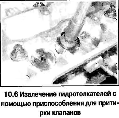
6. Remove the hydraulic tappets from the cylinder head and place them in a separate numbered bag (see photo). The hydraulic tappet should be stored in such a way that oil does not leak out of it.
7. Check the condition of the camshaft beds and covers. If visible signs of wear are detected, replace the cylinder head and camshafts.
8. Check the camshaft runout in the prisms. If the runout exceeds the norm, replace the camshaft.
9. Check the condition of the hydraulic tappet surface and the holes in the cylinder head. If severe wear is detected, replace the tappet.
Installation
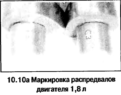
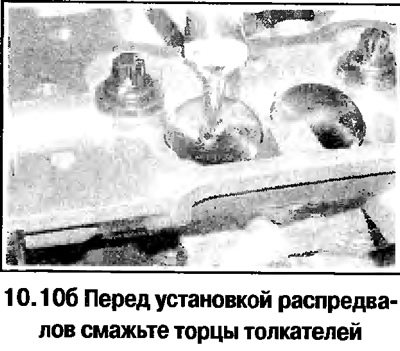
10. Before assembly, lubricate the ends of the tappets with molybdenum disulfide grease and install both camshafts in place so that the cams of the 1st cylinder are facing up (see photo). The intake camshaft of the 1.8 L engine has the SZ marking, and the exhaust camshaft has the TZ mark (see photo).
11. Temporarily replace the camshaft sprockets and align the camshafts so that the location of the marks on the sprockets approximately corresponds to TDC. Remove the sprockets.
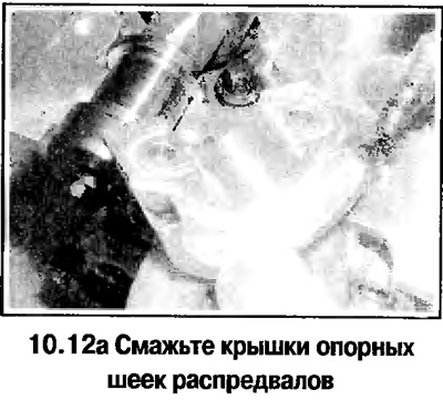
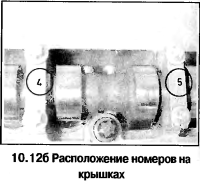
12. Lubricate the camshaft covers and install them in place (based on the location of the rooms) and gradually tighten the cap bolts in the spiral pattern shown (see photo). First tighten the bolts until the split surfaces of the covers and beds touch, then tighten the bolts to the specified torque.
13. Perform the above steps for the exhaust camshaft.
14. Install the removed parts in reverse order.
Visitor comments