


Half shafts
The axle shafts are shown in the figure 5.85.
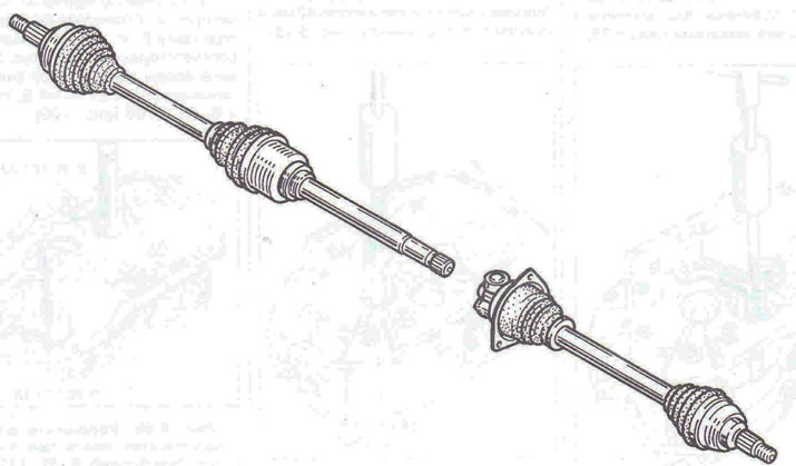
Figure 5.85. Half-shafts.
Removal and installation axle shafts
Removal
1. Place the vehicle on a two-post lift.
2. Remove the front wheels and unscrew the hub nut.
3. Unscrew the nut securing the ball joint pin of the steering rod B and the bolts of the lower mounting of the shock absorber strut C (figure 5.86).
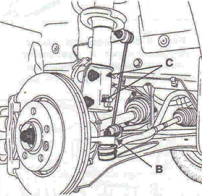
Figure 5.86. Unscrew the nut securing the ball joint pin of the steering rod B and the bolts of the lower mount of the shock absorber strut C.
4. Remove the outer axle joint tailpiece from the steering knuckle by tilting it to do so.
On the right side
5. Unscrew the two bolts A securing the intermediate support (figure 5.87).
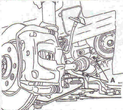
Figure 5.87. Unscrew the two bolts A securing the intermediate support.
6. Remove the axle shaft from the axle shaft drive gear.
On the left side
7. Drain the oil from the gearbox.
8. Unscrew the three bolts securing the inner axle joint boot holder to the gearbox (figure 5.88).
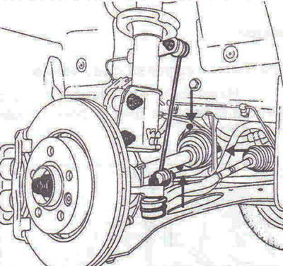
Figure 5.88. Unscrew the three bolts securing the inner axle joint boot holder to the gearbox.
9. Remove the axle shaft from the gearbox.
Installation
On the left side
10. Remove the plastic cover of the axle shaft bearing boot, trying to keep it in a horizontal position. The axle shaft should slide in easily so that the threaded portion that will be screwed onto the hub nut comes out (figure 5.89).
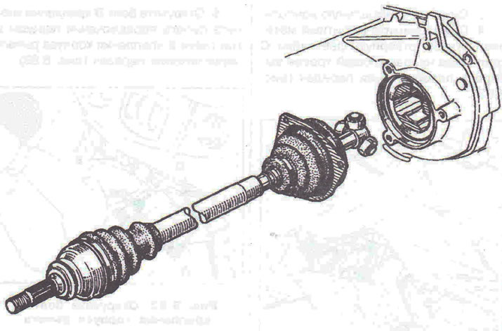
Figure 5.89. The axle shaft should slide in easily so that the portion of the thread that will be screwed onto the hub nut comes out.
On the right side
11. Clean the intermediate support bore for the bearing. Check the condition of the oil seal seat on the intermediate shaft.
Note: It is recommended to replace the differential flange seal each time the right axle shaft is removed.
12. Further installation is carried out in the reverse order of removal.
Visitor comments