
Removing
1. Disconnect the wire terminal from the battery «masses» (-).
2. Apply the parking brake, jack up the front of the vehicle and jack it up securely.
3. Unscrew the bolts and remove the mudguard (protection) engine compartment.
4. Unscrew the bolts and remove the heat shield of the hydraulic modulator.
5. Disconnect the supply line coming from the power steering pump. Substitute a container under the joint to be separated to collect the escaping liquid.
6. Remove the cover of the fuse block in the engine compartment and disconnect the block from the holder.
7. Remove the cover of the relay box in the engine compartment. Remove the engine control unit and disconnect the multi-pin plug from it.
8. Remove the engine control unit relay.
9. Disconnect the three plugs from the fuse box in the engine compartment.
10. Remove as much fluid as possible from the power steering reservoir.
11. Loosen the fastening clamps and disconnect two hoses from the power steering reservoir. Substitute a container under the joint to be separated to collect the escaping liquid.
12. Remove the power steering reservoir from the mounting bracket, then unscrew the bracket mounting bolts and remove it.
13. Unscrew a bolt of fastening and disconnect the multicontact plug of a plait of wires of the ABSAC electronic control unit.
14. Remove as much fluid as possible from the expansion tank of the brake system.
15. Unscrew union nuts and disconnect brake pipelines from the main brake cylinder. Substitute a container to collect the escaping liquid and plug the openings of the pipelines.
16. Label all six brake pipes of the hydraulic modulator so as not to confuse them during installation. Unscrew the nuts and remove the tubes from the modulator. Plug the brake pipes and hydraulic modulator ports to prevent excessive fluid loss and dirt ingress.
17. Disconnect the hydraulic modulator from the mounting bracket and remove it from the engine compartment, being careful not to tilt it so that fluid does not leak out.
Installation of the hydraulic modulator is carried out in the reverse order
18. Bring the fluid level in the power steering reservoir to normal.
19. Bleed the brake system (see relevant chapter).
20. Make sure the ABS warning light goes out after starting the engine.
21. Check the function of the system in the workshop using special diagnostic equipment.
Traction Control Switch Removal
22. Make sure the ignition key is in the «Off», then carefully pry the switch away from the instrument panel using a small screwdriver. Place cardboard or cloth under the screwdriver so as not to damage the instrument panel.
23. Disconnect the plug from the switch. The switch is installed in the reverse order of removal.
Front wheel speed sensor
Removing
24. Disconnect the wire terminal from the battery «masses» (-).
25. Tighten the parking brake lever, jack up the front of the car, place it on jack stands and remove the front wheel.
26. Release the sensor wire from the holders on the shock absorber strut of the front suspension and wheel arch. Do not confuse this wire with the brake pad wear sensor wire.
27. Unscrew the mounting bolt with a socket wrench and remove the sensor from the mounting bracket (see illustrations 17.27 and 17.27a).
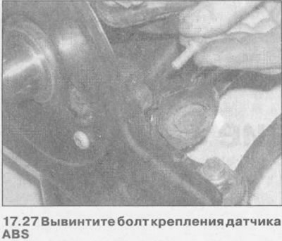
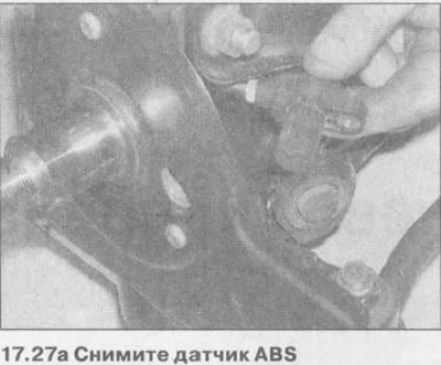
The ABS sensor is installed in the reverse order of removal Before installation, apply a small amount of protective grease to the sensor housing.
28. Check the function of the system in the workshop using special diagnostic equipment.
Rear wheel speed sensor
Removing
29. Disconnect the wire terminal from the battery «masses» (-).
30. Apply the parking brake lever, jack up the rear of the vehicle, place it on jack stands and remove the rear wheel.
31. Disconnect the sensor plug and release its wire from the mounts on the bottom.
32. Unscrew the mounting bolt and remove the ABS sensor (see illustration).
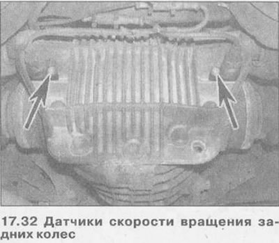
The rear wheel ABS sensor is installed in the reverse order of removal.
Apply a small amount of protective lubricant to the sensor housing before installation.
33. Check the function of the system in the workshop using special diagnostic equipment.
Visitor comments