


Contents: Removal ⬇ Installation ⬇
Removal
Note: If the vehicle has a high mileage, the old drive shaft should be replaced as a set. Right drive shaft (depending on the direction of travel) 346 mm longer than the left one.
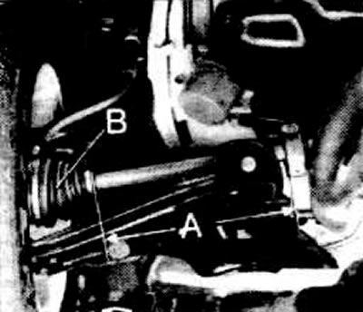
The right (long) drive shaft is subject to a two-part mass (cars with engines from 1.6 l and gearbox). When unscrewing, maintain a distance of A = 260 mm from the fastening of the outer hinge casing (B).
Loosen the drive shaft crown nut.
Place supports under the bottom, engage the gear, and set the handbrake.
Loosen the crown nut.
Caution: The vehicle must be supported on supports, otherwise there is a risk of accident.
Loosen the wheel nuts and lift the car.
Unpin the ball joint, unscrew the nut. Press out the ball joint with a special puller. See Figure A8288, item 12.1.
The article was published on the website OpelBook.ru
Caution: Since October 1982, drive shafts have been used which, unlike the previous shafts, do not have a stop against shear in the inner joint. If the joint is moved further than intended, the inner part of the joint may fall out of its outer part, and the drive shaft will lose its function.
Caution: When performing any work that involves removing the drive shaft from the gearbox housing, it is necessary to ensure that you can only pull on the joint, but not on the shaft. When removing and installing the drive shaft in the front wheel hub, do not forget this when working with the inner joint.
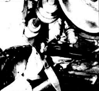
Knock out the drive shaft from the gearbox housing. In specialized workshops, a special device and a hammer weighing 1500 g are used for this.
Note: The jaws of the device always face the gearbox.
Gearbox F10 (1.2-/1.3-l engines). Knock out the drive shaft on the left side from the crankcase using the KM-460-2 or KM-460-1 device. The jaws of the device must face the gearbox.
Gearbox F16 (1.6-/1.8-l engines). On the left side, knock the drive shaft out of the crankcase using the KM-503 device; on the right side, push the drive shaft out of the crankcase using a crowbar.
Note: Since November 1983, modified drive shafts have been installed. These shafts have 3 thickenings in the longitudinal direction on the splines of the inner joint. When removing the shaft, pull on the joint, and under no circumstances on the shaft.
When removing the drive shaft, oil leaks out. Be sure to tightly close the drive shaft hole with a plug (ET-No. 9092869).
If you don't have a special tool at hand, you should knock out the drive shaft with a flat chisel. In this case, you must first remove the differential cover.
Caution: Oil will start to leak out.
Insert a flat chisel between the end of the shaft and the bevel gear shaft and push out the shaft.
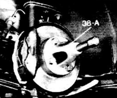
Pull the drive shaft out of the wheel hub by hand. If this is not possible, then push it out with a special puller.
Installation
Caution: Handle the new shaft with care. The shaft should not lie on the joint housings for a long time.
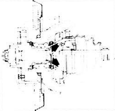
All contact surfaces of the outer joint, as well as the surface of the hub bearing, must be absolutely clean.
Lubricate the shaft teeth with transmission oil.
Insert the drive shaft into the hub.
Screw on a new castle nut with a new washer.
Lubricate the junction of the drive shaft and the gearbox housing with transmission oil.
Install a new snap ring.
Caution: Do not overtighten the retaining ring.
Press the drive shaft into the gearbox housing by hand. Then press the retaining ring with a screwdriver until it catches.
Insert the screwdriver into the thickening, not into the casing.
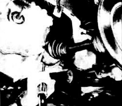
After inserting the retaining ring into the groove, check the strength of the installation.
If the differential cover was removed, attach the cover with a new gasket. Glue the new gasket to the cover with plastic grease. Secure with bolts with a force of 30 Nm.
Install the ball joint, tighten the crown nut to 75 Nm.
Note: If the cotter pin does not fit, tighten the nut longer until the position and hole for the cotter pin match. Cotter the ball joint.
Screw on the wheel, lower the car.
Secure the drive shaft with a new crown nut and a new washer to a torque of 100 Nm.
Loosen the nut and tighten it again with a force of 20 Nm.
Place a torque wrench on the crown nut and use chalk to mark 90° on the tires. To do this, start from the wrench and use chalk to mark every 1/4 turn.
Note: If the cotter pin cannot be inserted, loosen the nut rather than tighten it until the position and hole for the cotter pin match.
Secure the nut with a cotter pin.
Tighten the wheel mounting bolts crosswise to 90 Nm.
Fill with transmission oil.
Visitor comments