


Contents: Removal ⬇ Installation ⬇
Removal
1. Remove the steering wheel.
2. Move the column to the lower position and lock it with the key.
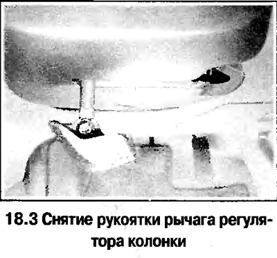
3. Loosen the screw and remove the column control lever handle (see photo).
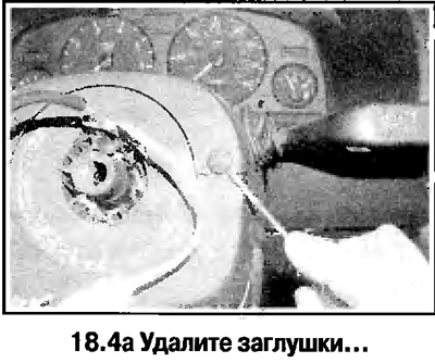
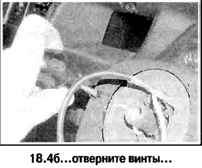
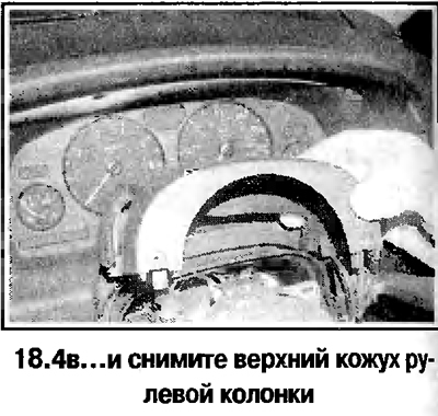
4. Remove the plugs, unscrew the screws and remove the upper steering column cover (see photos).
5. Remove the 2 upper and 1 lower screw and remove the lower steering column cover (see photo).
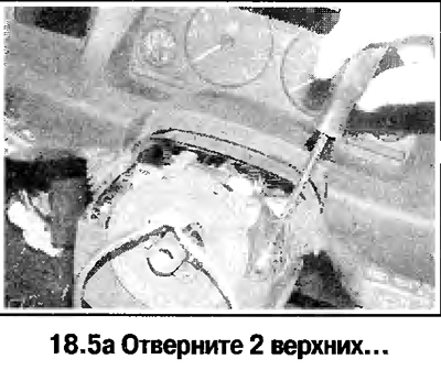
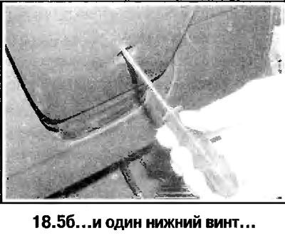
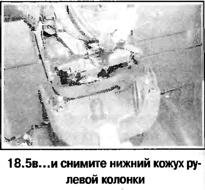
6. Pry and disconnect the airbag module connector.
7. Remove the brackets and remove the contact device from the steering column.
Attention! Later models are equipped with a contact device lock, which ensures that the device is fixed in a symmetrical position. It is prohibited to unlock the lock after removing the contact device.
8. Remove the turn signal and windshield wiper switches from the column housing (Chapter 12).
9. Remove the ignition key, pry up and remove the round cover.
10. Insert and turn the ignition key to the ACC position, press the lock plunger with a screwdriver and remove the ignition switch from the steering column cover (see photo).
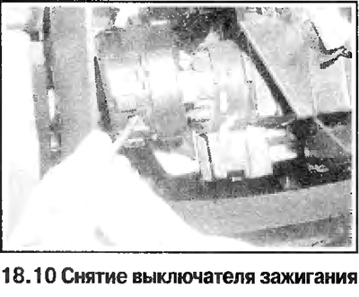
11. On some vehicles, remove the immobilizer unit by doing the following. Disconnect the wires from the unit, press the latches and remove the unit from the ignition switch housing. Remove the drum lock switch. On some vehicles, the design of the immobilizer mount is slightly different. On these models, remove the column lock drum (Chapter 12). Bend back the latches and remove the unit from the ignition switch housing, remove the cuff and disconnect the wire.
12. Remove the column spring cover and tension spring (see photos).
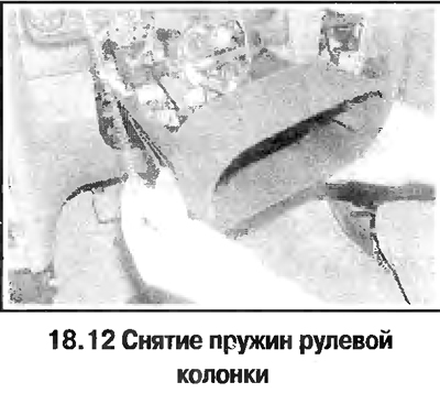
13. Disconnect the wiring from the steering column by removing it from the brackets, remove the panel in the footwell on the driver's side and the heater air duct.
14. Mark the relative position of the column shaft and the upper universal joint and unscrew the joint clamp bolt. Remove the lower part of the column shaft from the joint splines (please note that the intermediate shaft has a telescopic design).
15. On models equipped with ESP system (electronic stabilization system) disconnect the steering angle sensor wire connector from the steering column. Press the latches, remove the sensor and slide it down the column.
16. Unscrew the lower clamp bolt and the upper column mounting bolt (see photo). On some vehicles, remove the retainer. On models equipped with ESP, lift the column up and remove the sensor from the column through its lower part.

17. Remove the column, paying attention to the number and location of the gasket pack under the lower column clamp bracket.
Installation
18. Install the lower column clamp, loosen the lower clamp bolts. Install the column in the clamp. On models with an ESP system, place the steering angle sensor ring on the column, aligning the tooth on the sensor with the groove on the column.
19. On 2000 and later models, install the upper column mounting bolts and tighten them to the specified torque.
20. On some models up to and including 1999, install the gasket packs in place under the lower clamp bracket and tighten the clamp and upper column mount bolts to the specified torque.
21. On pre-1999 models that did not have gasket packs, install a 4.0mm thick gasket pack (4 gaskets of 1.0 mm, purchased at a car service center) under the lower clamp bracket, tighten the clamp bolt to the specified torque. Then try to move the lower part of the column upwards - the gray guide bushing at the bottom of the column should remain stationary. Otherwise, remove one gasket at a time until the bushing remains stationary. When finished, tighten the upper column mounting bolts to the specified torque.
22. Then assembly is carried out in reverse order.
Visitor comments