


Contents: Key to Figure 12.87 ⬇ Explanations ⬇
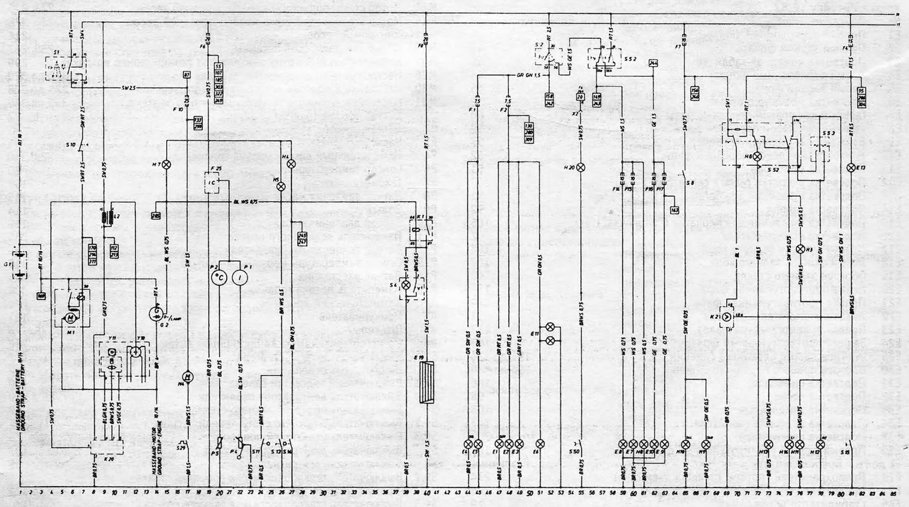
Open large image in new tab →
Figure 12.87. Electrical diagram for models produced before 1983 (continuation)
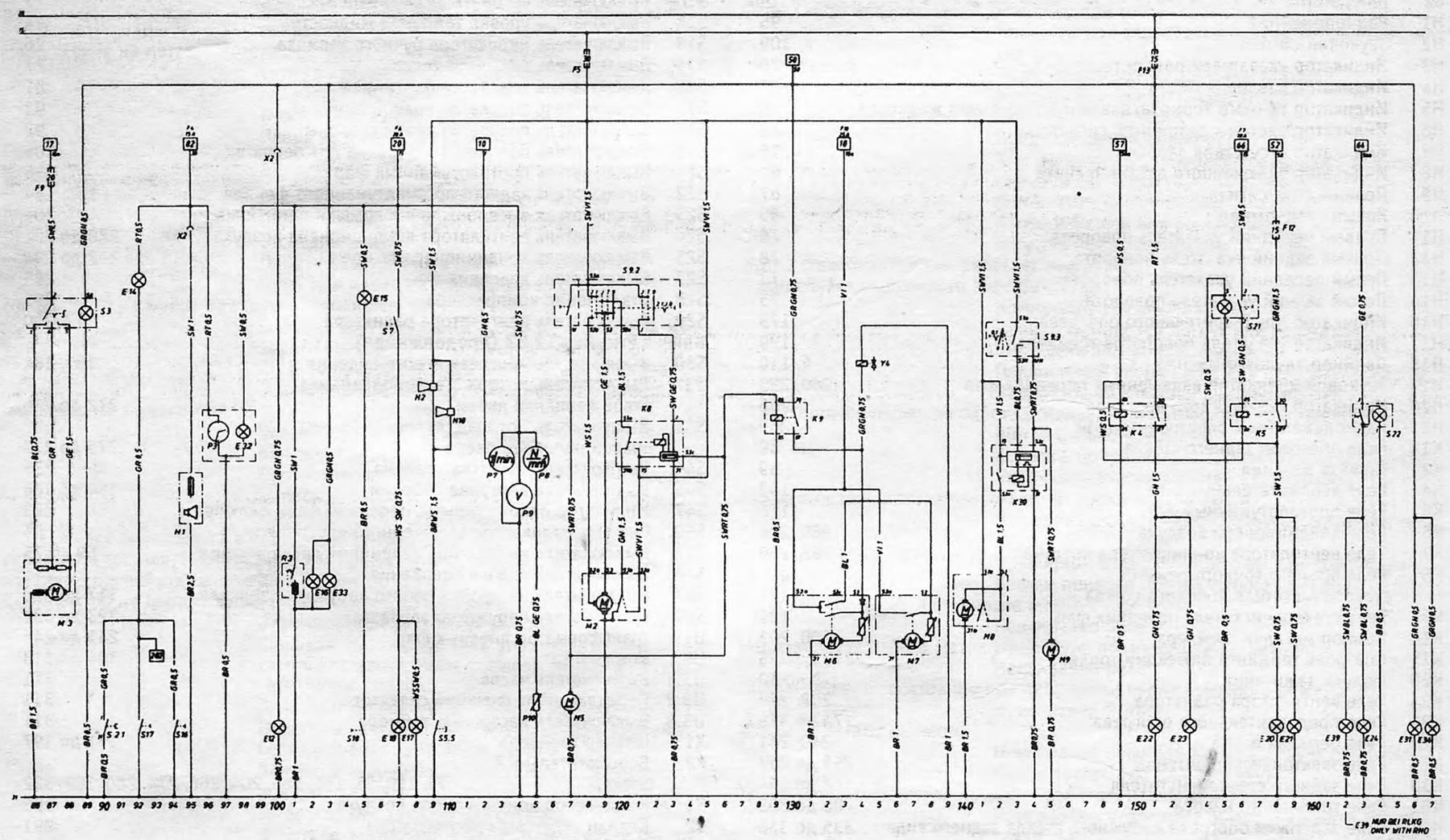
Open large image in new tab →
Figure 12.87. Electrical diagram for models produced before 1983 (continuation)
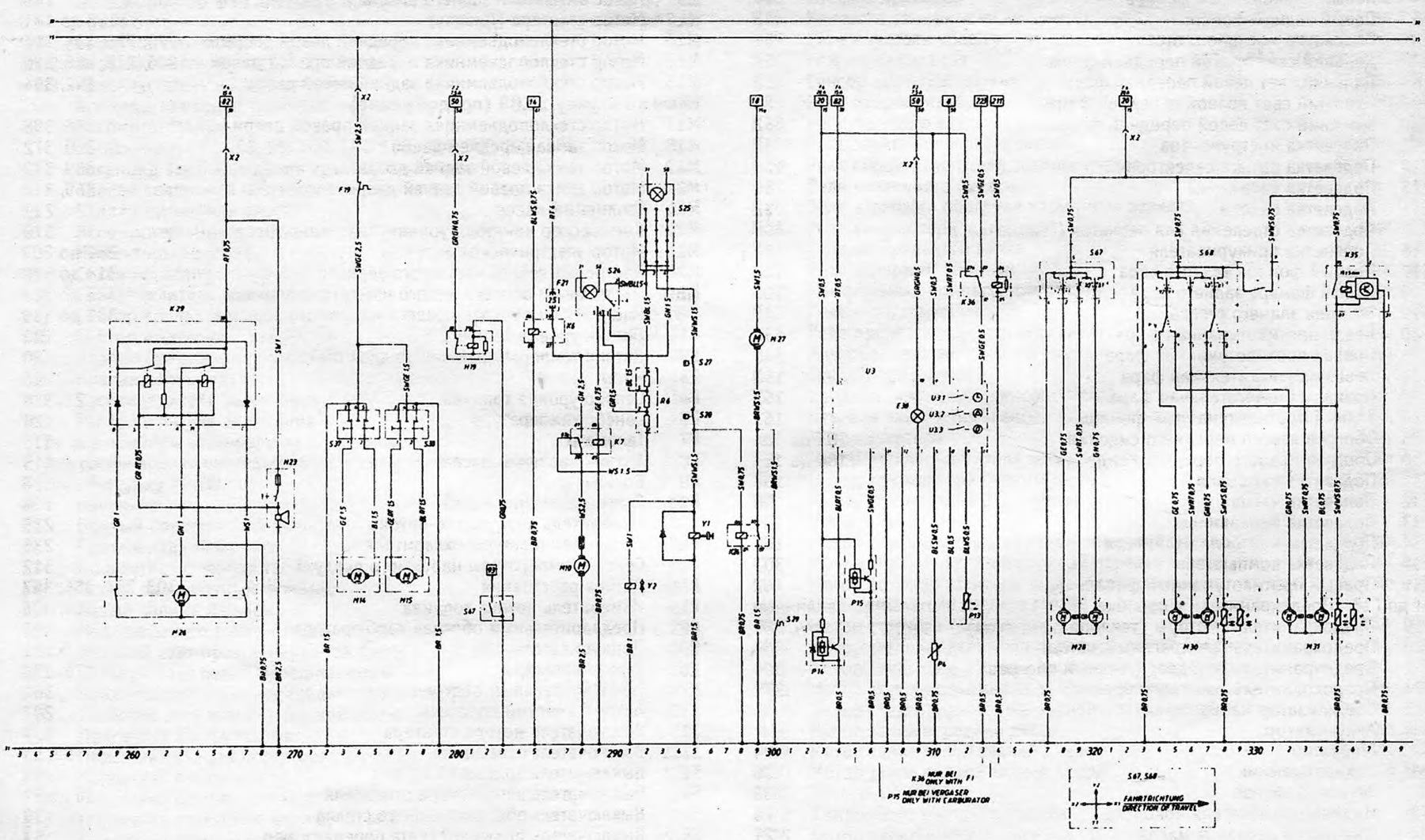
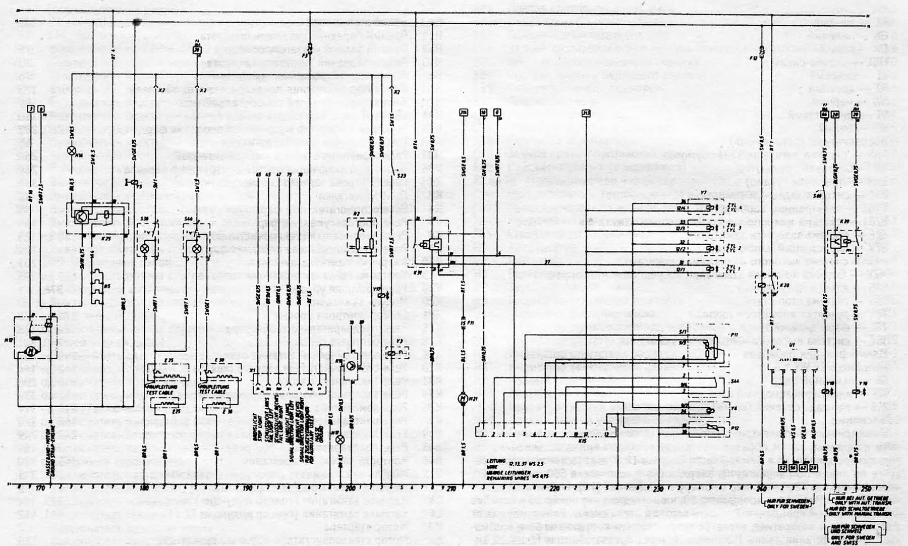
Open large image in new tab →
Figure 12.87. Electrical diagram for models produced before 1983 (continuation)
Key to Figure 12.87
| № | Description | Chain coordinate |
| E1 | Right parking light | 47 |
| E2 | Right rear light | 48 |
| EZ | Number plate illumination | 49 |
| E4 | Left parking light | 44 |
| E5 | Left rear light | 45 |
| E6 | Engine bay lighting | 52 |
| E7 | Main beam of the right front headlight | 60 |
| E8 | Main beam of the left front headlight | 59 |
| E9 | Low beam right front headlight | 63 |
| E10 | Low beam left front headlight | 62 |
| E11 | Instrument lighting | 51 |
| E12 | Selector lever handle illumination | 100 |
| E13 | Luggage compartment lighting | 81 |
| E14 | Interior lighting | 92 |
| E15 | Illumination of the glove compartment ("glove box") | 105 |
| E16 | Cigarette lighter illumination | 102 |
| E17 | Right reversing light | 108 |
| E18 | Left reversing light | 107 |
| E19 | Rear window heating | 40 |
| E20 | Left fog light | 158 |
| E21 | Right fog light | 159 |
| E22 | Left auxiliary headlight | 151 |
| E23 | Right auxiliary headlight | 153 |
| E24 | Rear fog light | 163 |
| E25 | Left front seat heating | 181 to 184 |
| E30 | Heated right front seat | 186 to 189 |
| E31 | Symbol highlighting | 166 |
| E32 | Clock backlight | 98 |
| EZZ | Ashtray illumination | 103 |
| E34 | Heater control backlight | 167 |
| E38 | Computer backlight | 309 |
| E39 | Right rear fog light | 162 |
| F1 to F8 | Fuses in the box | Various |
| F19 | Fuse (window lift motors) | 274 |
| F21 | Fuse (air conditioner) | 286 |
| F25 | Voltage stabilizer | 19 |
| G1 | Battery | 1 |
| G2 | Generator | 14 |
| H1 | Radio | 95 |
| H2 | Sound signal | 109 |
| NZ | Direction indicator | 76 |
| H4 | Oil pressure indicator | 27 |
| H5 | Handbrake/Brake Fluid Pressure Indicator | 26 |
| H6 | Hazard warning system indicator | 72 |
| H7 | No charge indicator | 15 |
| H8 | High beam indicator | 61 |
| H9 | Right brake light | 67 |
| H10 | Left brake light | 65 |
| H11 | Right front turn signal | 76 |
| H12 | Right rear turn signal | 78 |
| H13 | Left front turn signal | 73 |
| H14 | Left rear turn signal | 75 |
| H16 | Preheating indicator | 173 |
| H17 | Trailer Direction Indicator | 199 |
| H18 | Double beep | 110 |
| H19 | Sound indicator of headlights on | 280, 283 |
| H20 | Throttle on indicator | 55 |
| H23 | Radio receiver with electric antenna | 269 |
| K1 | Rear window heating relay | 39 |
| K2 | Flashing device | 69 |
| K4 | Auxiliary headlight relay | 149 |
| K5 | Fog light relay | 156 |
| K6 | Air Conditioner Relay | 285, 286 |
| K7 | Air Conditioner Fan Relay | 288, 289 |
| K8 | Windshield wiper intermediate mode relay | 120 to 123 |
| K9 | Headlight wiper relay | 129 |
| K10 | Trailer Flasher Device | 200, 201 |
| K15 | Fuel injection timing control | 213 to 225 |
| K20 | Ignition module | 8 to 10 |
| K24 | Radiator Fan Relay | 298, 299 |
| K25 | Preheating relay | 174 to 178 |
| K28 | Running Light Relay | 240, 241 |
| K29 | Electric Antenna Relay | 259 to 267 |
| K30 | Rear wiper relay | 142 to 144 |
| K31 | Fuel pump relay | 206 to 208 |
| KZ5 | Rear view exterior glass heating delay relay | 335 to 338 |
| K36 | Computer relay | 312 to 314 |
| KZ9 | Time delay relay | 247 to 249 |
| M1 | Starter motor | 7 |
| M2 | Windshield wiper motor | 119 |
| M3 | Heater Fan Motor | 89 |
| M4 | Radiator Fan Motor | 17 |
| M5 | Windscreen washer pump | 117 |
| M6 | Left Front Headlight Wiper Motor | 130 |
| M7 | Right Front Headlight Wiper Motor | 135 |
| M8 | Rear Window Wiper Motor | 140 |
| M9 | Rear window washer pump | 145 |
| M10 | Air conditioner fan motor | 288 |
| M12 | Starter motor (diesel) | 168 to 171 |
| L1,2 | Ignition coil | 9,10 |
| M14 | Left front door window lift motor | 273, 275 |
| M15 | Right front door window lift motor | 276, 278 |
| M21 | Fuel pump | 211 |
| M26 | Electric Antenna Motor | 259, 267 |
| M27 | Auxiliary fan motor (air conditioner) | 299 |
| M28 | Adjusting the left outside mirror | 318 to 320 |
| M30 | Adjusting and heating the left outside mirror | 325 to 328 |
| M31 | Adjusting and heating the right outside mirror | 332 to 335 |
| R1 | Fuel level sensor | 22 |
| R2 | Temperature sensor | 20 |
| RZ | Watch | 96 |
| R4 | Fuel level measuring sensor | 22, 310 |
| R5 | Temperature sensor | 20 |
| R7 | Tachometer | 113 |
| R8 | Oil pressure sensor | 115 |
| P9 | Voltmeter | 114 |
| P10 | Oil pressure sensor | 115 |
| R11 | Air flow meter | 235 |
| R12 | Coolant temperature sensor | 235 |
| R13 | Outside air temperature sensor | 312 |
| R14 | Distance sensor | 303, 304 |
| R15 | Fuel flow meter | 305, 306 |
| R2 | Automatic throttle | 202 |
| R3 | Cigarette lighter | 101 |
| R5 | Plugs | 175, 176 |
| R6 | Air Conditioner Fan Resistor | 292 |
| S1 | Starter motor switch | 6,7 |
| S2 | Light switch | 52 |
| S2.1 | Interior light switch | 90 |
| S3 | Heater Fan Switch | 86 to 89 |
| S4 | Rear window defroster switch | 39 |
| S5.2 | Headlight low beam switch | 57 |
| S5.3 | Turn signal switch | 78 |
| S7 | Reverse light switch | 107 |
| S8 | Brake light switch | 65 |
| S9.2 | Windshield wiper switch (intermediate mode) | 117 to 121 |
| S9.3 | Rear Window Wiper Switch (intermediate mode) | 143, 144 |
| S10 | Automatic transmission switch | 7 |
| S11 | Brake fluid level switch | 24 |
| S13 | Handbrake indicator switch | 26 |
| S14 | Oil pressure switch | 27 |
| S15 | Trunk light switch | 81 |
| S16 | Right side light switch | 93 |
| S17 | Left side light switch | 92 |
| S18 | Glove compartment light switch | 105 |
| S21 | Fog light switch | 156 |
| S22 | Rear fog light switch | 163, 164 |
| S23 | Trunk lid release switch | 204 |
| S24 | Air Conditioner Fan Switch | 288 to 291 |
| S25 | Air conditioner switch | 292 to 294 |
| S27 | Pressure switch | 295 |
| S28 | Compressor shutdown | 295 |
| S29 | Radiator Fan Switch | 17,300 |
| S30 | Left seat heating switch | 181, 181 |
| S37 | Left front door window lift motor switch | 272 to 275 |
| S38 | Right front door window lift motor switch | 276 to 279 |
| S44 | Valve handle switch | 235 |
| S46 | Seat heating switch | 184 to 186 |
| S47 | Door open indicator/headlights on | 283 |
| S50 | Throttle On Indicator System | 55 |
| S52 | Hazard warning light switch | 69 to 75 |
| S60 | Clutch pedal switch | 246 |
| S67 | Left outside mirror adjustment switch | 317 to 320 |
| S68 | Outside mirror switch | 323 to 332 |
| U1 | Daytime running lights transformer | 241 to 245 |
| U3 | Computer | 304 to 313 |
| U3.1 | Clock switch | 311 |
| U3.2 | Selector function switch | 311 |
| U3.3 | Setting/Timer Switch | 311 |
| X1 | Trailer plug | 191 to 197 |
| X2 | Auxiliary plug | 95, 100, 55, 181,185, 204, 266, 274, 280, 309, 322 |
| Y1 | Air conditioner compressor | 295 |
| Y2 | Accelerator solenoid valve | 291 |
| Y3 | Trunk Lid Release Solenoid | 204 |
| Y4 | Headlamp Washer Solenoid Valve | 134 |
| Y5 | Diesel Solenoid Valve | 179 |
| Y6 | Auxiliary air valve | 235 |
| Y7 | Fuel injectors | 235 |
| Y10 | Distributor | 12 |
| Y11 | Sensor | 9,10 |
| Y17 | Idle Speed Interrupt Solenoid Valve | 203 |
| Y18 | Solenoid valve | 246, 249 |
Not all devices and equipment are installed on all models
Color coding
- BL — blue
- BR — brown
- GE - yellow
- GN - green
- GR — gray
- HBL - light blue
- LI — purple
- RT - red
- SW - black
- VI - purple
- WS — white
Abbreviations (abbreviations)
- ABS - anti-locking brake system
- BR — on-board computer
- EMR - receiver (radio)
- EST - ignition delay system (electronic)
- EV61 - electronic carburetor
- EZ61 - Microprocessor Ignition Retard System
- EZF - ignition delay system
- EZV - Electronic Carburetor
- HEI - High Voltage Ignition System
- MZV - Microprocessor-based ignition control system
- SAS — interrupter valve
- SSS - stop-start system
- TBI - Fuel Injector Handle
- TFL — daytime running lights
- TSZ - High Voltage Ignition System
Article published on the website: OPELBOOK.ru
Wire identification eg: GE WS 1.5
- GE - Primary color
- WS - identification color
- 1.5 — cross-sectional area (sq mm)
Explanations
The electrical diagrams below are drawn using a coordinate system such that the ground line is at the bottom. Using coordinate 55 at the bottom of Figure 12.87 as an example, follow the line up past switch S50 to lamp H20, through connector X2 and finally to the number in the box (20). Return again to the bottom of the Figure, to coordinate 20, and you will see that the number 55 in the box matches this coordinate near the top of the diagram. The line running from this number in the square is a continuation of coordinate 55 and indicates the power supply wire for the H20 lamp, which goes through the 20 Amp fuse F6.
Visitor comments