
Examination
1. Clean the back of the bushing and its mounting location in the cylinder block and main bearing caps.
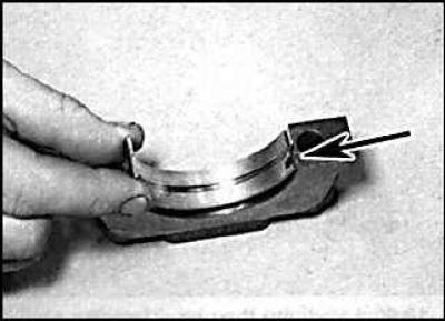
2. Install the inserts in their places, while the protrusion on the insert should be aligned with the groove on the cover (indicated by an arrow).
3. One method, which involves having a micrometer to measure the diameter of the bores, is to install the main bearing caps along with the bushing on the cylinder block and screw them to the required torque. Measure the inside diameter of each assembled pair of bearing shells. Measure the diameter of each crankshaft main journal. Subtract the corresponding diameter of the crankshaft main journal from the measured bearing diameter.
4. Second (and more accurate) the method is to use a product known as Plastigage. This is a round plastic rod that is compressed between the bushing and the crankshaft journal. After removing the main bearing cap, the deformed plastic rod is measured with a special gauge, which is included in the Plastigage kit. On the liners installed in the cylinder block, install the crankshaft without lubrication. The crankshaft journals and liners must be perfectly clean and dry.
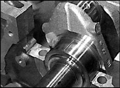
5. Cut off a few pieces of the plastic Plastigage rod (they should be slightly shorter than the width of the main bearings) and install on each crankshaft journal.
6. Install the covers with the bottom liners and tighten the mounting bolts to the required torque. Do not rotate the crankshaft while measuring clearance with the Plastigage method.
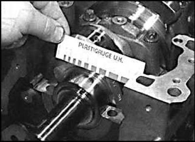
7. Unscrew the cover of the insert attachment, remove it and attach a scale ruler to the deformed plastic rod. By comparing the width of the deformed plastic rod with the reference width on the scale bar, determine the amount of gap.
8. Finally, carefully clean any traces of Plastigage from the liners and crankshaft.
Visitor comments