
Engine idle adjustment
The idle speed of the engine crankshaft is adjusted by screw 2 (see photo) idle air control.
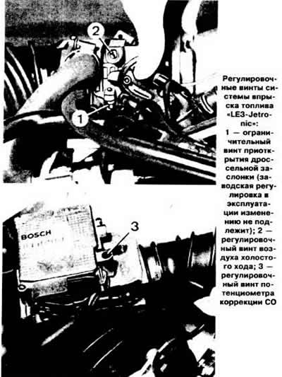
To adjust the CO content, remove the plug of the adjusting screw 3 of the CO correction potentiometer, use the screw to set the required CO content, and then put the plug back in place.
Throttle position sensor test
Make sure the ignition is off. Disconnect the ECU connector (see picture).
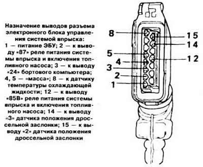
Connect an ohmmeter to the leads «15» And «5» ECU connector, turn on the ignition and measure the resistance, which should be zero.
Open the throttle and measure the resistance, which should be equal to infinity.
Connect an ohmmeter to the leads «14» And «5» ECU connector and measure the resistance, which should be equal to infinity. When the throttle is opened at least 60% of the way, the resistance should drop to zero.

If the ohmmeter reading is abnormal, disconnect the throttle connector (see picture) and repeat the above resistance test by connecting an ohmmeter accordingly to the terminals «18» And «2» And «18» And «3» sensor pads.
If the resistance values are still out of specification, replace the throttle position sensor. If after installing a new sensor, the ohmmeter readings returned to normal. check the wires and their connections and eliminate the detected faults.
Throttle Position Sensor Adjustment
Loosen the two screws securing the sensor, turn the sensor to the right, then slowly to the left until a click is heard on the microswitch. In this position, tighten the sensor fixing screws.
Checking the air flow meter
Disconnect the cable from the negative battery terminal and remove the computer from the air flow meter.
By pressing the pressure disk of the air flow meter, check the smoothness of its movement from one extreme position to another. If necessary, remove resinous deposits with any solvent suitable for this purpose.
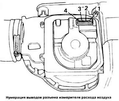
Connect an ohmmeter in turn to the pairs of terminals of the meter block (see picture) «2» And «4», «4» And «3», «4» And «1» and compare the instrument readings with the required values specified in subsection «Design and specifications».
Fuel pressure test
Disconnect the fuel supply hose from the fuel line and attach a pressure gauge to the holes in the hose and fuel line.
Start the engine at idle and measure the fuel supply pressure on the pressure gauge, which should be 2.0 kg / cm2. Disconnect the vacuum hose from the fuel pressure regulator and check that the fuel pressure has increased by about 0.5 kg/cm2.
Stop the engine and monitor the fuel pressure on the gauge. If the pressure drops, pinch the hose from the fuel pump to the fuel line to check the fuel pump check valve is working. Pinch the fuel drain hose into the tank under the pressure regulator to check the tightness of the non-return valve. After that, check for fuel leakage through the injectors, as indicated in subsection «fuel injection system «LE-Jetronic».
Checking the Fuel Pressure Regulator
Start the engine and check the fuel supply pressure. Disconnect the vacuum hose from the pressure regulator, attach a vacuum pump to the regulator and create a vacuum of 0.5 kg / cm2. In this case, the fuel pressure should decrease by 0.5 kg / cm2.
Checking the auxiliary air valve
On a cold engine
With the engine idling, pinch the hose connecting the auxiliary air supply valve to the intake manifold. In this case, the engine speed should decrease.
On a warm engine
Make sure the auxiliary air damper damper is fully closed. Pinch off the hose connecting the auxiliary air supply valve to the intake manifold. In this case, the engine speed should decrease by no more than 50 rpm.
Visual check
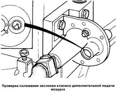
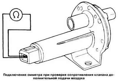
Disconnect both air hoses from the valve and visually check the position of the damper through the valve openings (see picture). On a cold engine, the valve flap should be open.
Connect air hoses to valve
Disconnect the air hoses from the valve and visually check the position of the valve flap, which should be closed.
Resistance test
Disconnect the valve connector, connect an ohmmeter to the terminals of the valve block (see picture) and measure the resistance, which at a temperature of 20°C should be 40 ohms.
Checking the Spray Cone and Nozzle Leaks
Remove the fuel line, injectors and fuel pressure regulator from the engine. Disconnect the pads from the injectors.
Install the injectors on the fuel line, attach the fuel pressure regulator, fuel supply and drain hoses and place the injection injectors over a suitable container.
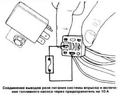
Remove the relay for powering the injection system and turning on the fuel pump and connect the output «30» relay pads (red wire) with conclusion «87b» (red-black wire) wire bundle connector via 10 A fuse (see picture), thereby activating the fuel pump.
Check for leakage of fuel drops through the injectors, which should not exceed one drop per minute, and replace leaking injectors.
By connecting a 12 V DC source to each nozzle in turn, check the shape of the spray cone (see picture in subsection «fuel injection system «LE-Jetronic»).
Checking the resistance of the injector winding
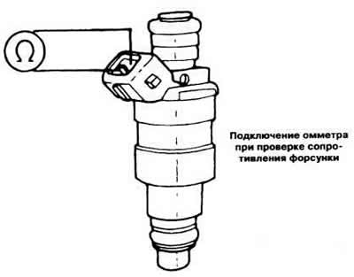
Alternately connecting an ohmmeter to the terminals of each injector (see picture), check the resistance, which should be in the range of 15-17 ohms.
Checking the ignition timing control circuit of the electronic control unit
Make sure the ignition is off. Disconnect the ECU connector and connect a voltmeter to the terminals «5» And «1» ECU pads (see picture).
Turning the crankshaft of the engine with a starter, check for voltage fluctuations. If there is no voltage fluctuation, check the circuit between the terminal «1» (—) ignition coils and output «1» ECU pads for wire breaks and short circuits.
Checking the supply voltage of the electronic control unit
Disconnect the ECU connector and turn on the ignition.
Connect a voltmeter to the leads «2» And «4», «5» ECU pads. If the voltmeter shows a different voltage than the battery voltage, perform the following checks:
- check for battery voltage at terminal «30» power relay for the injection system for turning on the fuel pump. If the voltmeter shows low voltage or no voltage. recheck the continuity between the terminal «1» (—) ignition coils and output «1» ECU pads, as well as an ignition switch;
- check for battery voltage at terminal «86» relay;
- check relay connection for «mass», by connecting an ohmmeter to the output «85» relay and to «mass». If connection with «weight» OK, the ohmmeter will show R=0.
Visitor comments