
Removing
Attention.
- To prevent personal injury and/or component damage, do not load the front wheels with the weight of the vehicle or drive with the driveshaft nut loose. This can cause the inner bearing race to separate, resulting in brake or suspension components being damaged and causing the vehicle to lose control.
- Driveshaft boots, seals, and clamps must be protected from sharp objects when servicing the driveshaft or components adjacent to it. Damage to the anthers, seals or clamps can cause the hinge to depressurize, which will lead to extraneous noise and possible drive shaft malfunctions.
1. Raise and secure the vehicle.
2. Remove the wheel with tire from the vehicle.
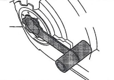
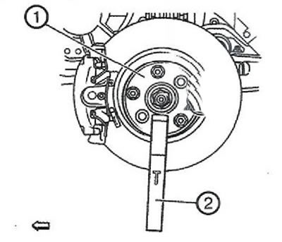
3. Install key CH-49376 (1) with extension EN-956-1 (2).
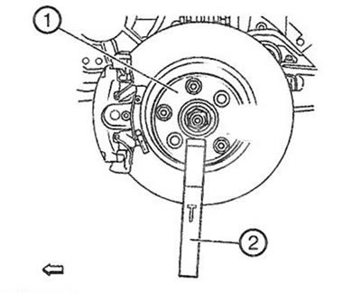
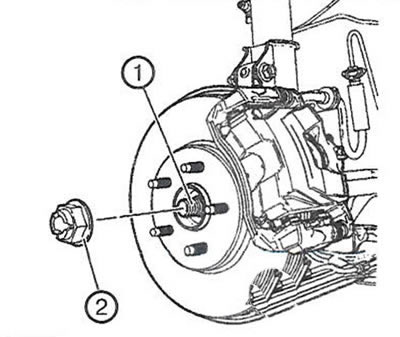
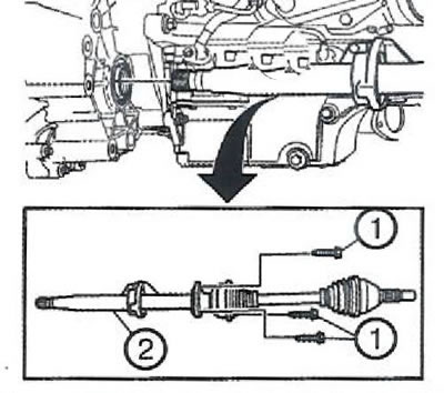
4. Loosen and discard the nut (2) from the drive shaft (1).
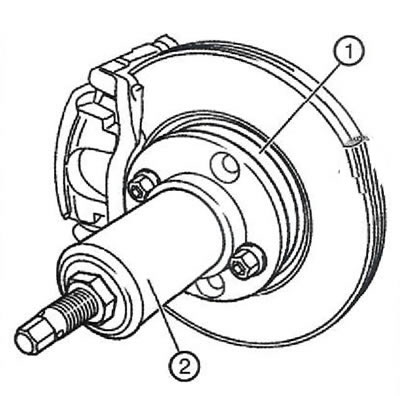
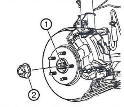
5. Using the CH-49400 puller (2), disconnect the brake disc from the wheel bearing/hub assembly (1).
6. Remove the outer tie rod end from the steering knuckle.
7. Disconnect the ball joint from the steering knuckle.
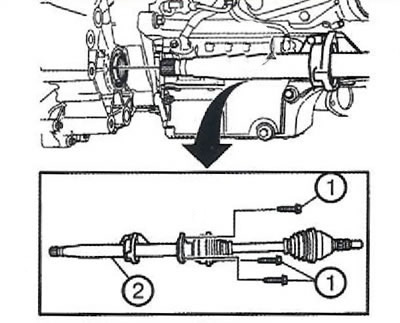
8. Remove three bolts (1) intermediate shaft flange.
- Press on new flange bearing.
Note. It is not possible to replace the bearing after the drive shaft has been installed.
9. Remove the drive shaft with intermediate shaft assembly (2) through the bracket.
10. If necessary, replace the inner joint with boot, otherwise discard the entire kit.
Installation
1. Replace intermediate shaft bearing:
- Remove retaining rings (1) And (4) and use a hydraulic press to remove the bearing (2) with flange (3).
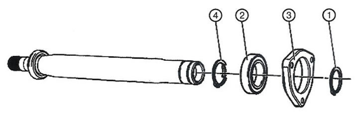
Press on new flange bearing.
Note. It is not possible to replace the bearing after the drive shaft has been installed.
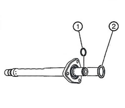
2. Replace retaining ring (1) and sealing ring (2).
3. Clean the contact surfaces of the intermediate and drive shafts with solvent.
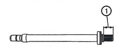
4. Apply Loctite 262 only to the drive shaft as shown (1). Ensure that there are no metal particles on the surface.
5. Assemble intermediate and drive shaft.
Note. The bonding process of the assembled intermediate and drive shafts lasts 72 hours at room temperature. Bonding must be done before or after installing the drive shaft on the vehicle. The vehicle must not move during the curing of the adhesive.
6. Install guard DT-6332 into differential output seal.
7. Carefully insert intermediate shaft assembly (2) into the differential so that the splines bypass the DT-6332 guard.
8. Remove guard DT-6332 from differential output seal. Install intermediate shaft assembly (2) into the differential until it is fully seated.
9. Install three bolts in the intermediate shaft flange and tighten to 22 Nm.
10. Install the front drive shaft into the wheel bearing/hub.
11. Install the ball joint on the steering knuckle.
12. Install the outer tie rod end on the steering knuckle.
13. Install a new nut (2) on the drive shaft (1).
14. Holding the hub from turning with the key CH-49376 (1) with extension EN-956-1 (2), tighten the drive shaft nut in three steps:
- Step one: Using a torque wrench with a suitable socket, tighten the drive shaft nut to 150 Nm.
- Loosen the nut by 45°.
- Tighten the drive shaft nut again to 250 Nm.
11. Install the wheel with tire on the car.
12. Lower the car.
13. Check the transmission oil level in the gearbox.
Visitor comments