


With separate modulator valve
1. With the engine off, press the brake pedal several times until it becomes firm enough to use up the vacuum in the vacuum booster.
2. Using a syringe, remove the brake fluid from the expansion tank of the master brake cylinder.
3. Remove the battery from the shelf.
4. Disconnect the electrical connector of the brake fluid level sensor.
5. Disconnect the expansion tank of the cooling system from the bracket and move it to the side to create free space.
6. Thoroughly clean the area of the modulator valve on the electronic brake control unit from accumulated dirt and foreign materials.
7. Loosen the six brake pipe connections (1). Plug the holes to prevent brake fluid from leaking out and dirt from getting in.
Note: Tightening torque: 18 Nm.
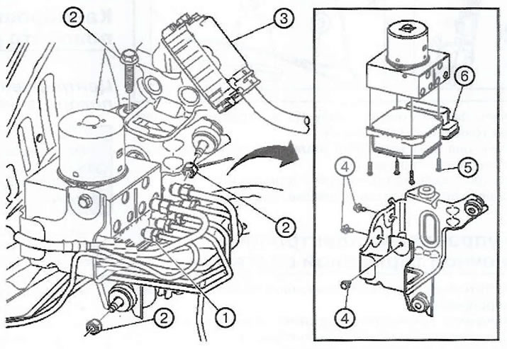
8. Loosen the three bolts (2) securing the electronic brake control unit.
Note: Tightening torque: 20 Nm.
9. Disconnect the electrical connector (3) of the brake system control unit and carefully remove the control unit.
Note: When installing a new ECU, apply grease to the electrical connector terminals.
10. Loosen the three bolts (4) of the brake system modulator valve.
Note: Tightening torque: 10 Nm.
11. Unscrew the four bolts (5) of the electronic brake control unit.
Note: Tightening torque: 3 Nm.
12. Carefully detach the electronic brake control unit (6) from the modulator valve. Do not pry off the components with an auxiliary tool.
13. Clean the sealing surfaces of the modulator valve with methyl alcohol and dry with a rag.
14. Installation is carried out in the reverse order of removal.
15. Fill the expansion tank of the master brake cylinder with brake fluid.
16. If a new electronic brake control unit is installed, program it.
17. Bleed the brake system.
18. Perform a diagnostic check of the system.
[Material copied from this website: opelbook.ru]
19. If equipped, calibrate the brake pedal position sensor.
20. Center the steering wheel angle sensor.
Without separate modulator valve
1. With the engine off, press the brake pedal several times until the pedal becomes firm to use up the vacuum reserve in the vacuum booster.
2. Using a syringe, remove the brake fluid from the expansion tank of the master brake cylinder.
3. Remove the battery from the shelf.
4. Disconnect the electrical connector of the brake fluid level sensor.
5. Disconnect the expansion tank of the cooling system from the bracket and move it to the side to create free space.
6. Thoroughly clean the brake line connection area from accumulated dirt and foreign materials.
7. Loosen the six brake pipe connections (1). Plug the holes to prevent brake fluid from leaking out and dirt from getting in.
Note: Tightening torque: 18 Nm.
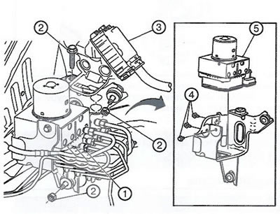
8. Unscrew the three fasteners (2) of the bracket of the electronic control unit of the brake systems.
Note: Tightening torque: 20 Nm.
9. Disconnect the electrical connector (3) of the brake system control unit and carefully remove the control unit assembly with the bracket.
Note: When installing a new ECU, apply grease to the electrical connector terminals.
10. Loosen the three mounting bolts (4) and remove the brake system control unit (5).
Note: Tightening torque: 10 Nm.
11. Installation is carried out in the reverse order of removal.
12. Fill the expansion tank of the master brake cylinder with brake fluid.
13. If a new electronic brake control unit is installed, program it.
14. Bleed the brake system.
15. Perform a diagnostic check of the system.
16. If equipped, calibrate the brake pedal position sensor.
17. Center the steering wheel angle sensor.
18. Program volatile memory.
Visitor comments