


2. Remove the trip meter pin.
Trip meter pin
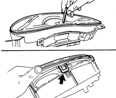
3. Lift the bars (arrows) and remove the cover.
Fuel gauge and temperature gauge
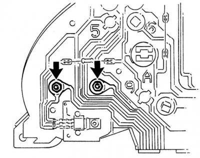
1. Remove the two mounting nuts (on models from 02.1994 - 4 nuts).
Fuel gauge mounting nuts
Speedometer
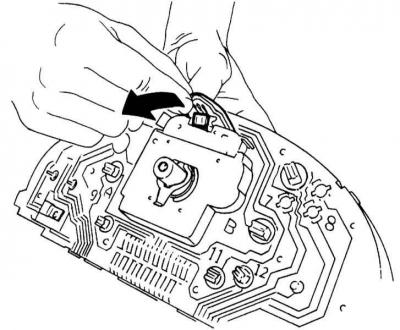
1. Carefully remove the printed circuit board.
Disconnecting the printed circuit board
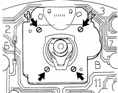
2. Remove the 4 mounting screws and remove the speedometer. For alternative versions from 02.1994, disconnect the speedometer connector using pliers and remove the 2 Torx T20 screws.
Speedometer mounting screws
Tachometer
1. Remove the three Torx T20 tachometer mounting screws from the front.
Voltage stabilizer
The voltage stabilizer performs the task of maintaining the on-board voltage at 12 V. If the stabilizer is damaged, among other things, an incorrect fuel reserve value is indicated.
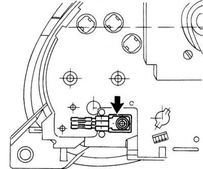
1. Unscrew the mounting screws and remove the stabilizer from the back of the instrument cluster, disconnect it from the contacts.
Voltage stabilizer mounting screws
2. Installation is carried out in reverse order.
Visitor comments