


Contents: Activation/deactivation of the…⬇ Selecting a temperature mode ⬇ Selecting the direction of air flow…⬇ Air circulation mode ⬇ Air conditioning mode ⬇ Exploitation techniques ⬇ Ventilation ⬇ Heating ⬇ Removal condensation from glass ⬇ Air conditioning (with appropriate…⬇
Activation/deactivation of the system and regulation of the air flow intensity
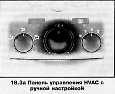
The rotary fan speed switch is located on the right side of the HVAC control panel (see illustration 18.3a). To activate the system, move the switch from position 0. Returning the regulator to the zero position allows you to turn off the system.
By moving the switch to the appropriate position, the fan operating speed mode is selected, from minimum (position 1) up to maximum (position 4).
Selecting a temperature mode
The temperature mode is selected using the rotary control located in the center of the panel (see illustration 18.3a). When turning the handle from the middle position to the left/right, the supply of cold or heated air will be increased accordingly.
Selecting the direction of air flow distribution
The direction of air flow distribution is selected using the rotary switch located on the left side of the system control panel (see illustration 18.3a), and provides the following options:
- Air supply to the face level and footwells.
- Air supply to the facial level.
- Supplying air to blow air into the windshield.
- Supplying air to the foot wells and to blow air onto the windshield.
- Supplying air to the footwells and the vehicle interior.
Air circulation mode
The air circulation mode is activated using the switch button on the control panel - the control LED built into the button should light up. In this mode, the supply of fresh air is turned off, which prevents exhaust gases, unpleasant odors, dust, and plant pollen, which causes allergic reactions, from entering the passenger compartment.
Note: Long-term use of the recirculation mode leads to fogging of the windows and increased air staleness, so it is recommended to activate this mode only if really necessary and for a relatively short time. As soon as the need for interior insulation disappears, the supply of fresh air should be resumed.
Pressing the switch button again restores the air supply.
Note: When the rotary switch for selecting the air flow direction (see above) is moved to the windshield air flow position, the air circulation mode is automatically switched off.
Air conditioning mode
The air conditioner operates in conjunction with the interior heating and ventilation system. In addition, the air conditioner is used for preliminary air drying.
On models with the corresponding configuration, the K/V is activated by pressing a button - the LED built into the button should light up. Deactivation occurs when the button is pressed again.
Note: When the outside temperature is low, the air conditioner will automatically turn off.
To cool the air in the cabin faster, you can temporarily activate the circulation mode (see above). If there is no longer a need for cooling and drying the air, turn off the air conditioner to save fuel.
Exploitation techniques
This section provides methods for setting up the basic operating modes of a manual HVAC system.
Ventilation
- Use the left rotary switch to select one of the three positions for the desired air distribution direction.
- Set the required temperature mode with the central rotary regulator - the interior will be blown by the oncoming air flow passing through the heat exchanger or bypassing it (depending on the position of the regulator);
- If necessary, use the right rotary switch to activate the system fan in the desired air flow intensity mode (1 to 4).
Heating
Note: The heating power depends on the coolant temperature and therefore reaches its maximum value only when the engine is warm.
To quickly warm up the interior:
- Select the desired air flow distribution direction;
- Turn the central control to the right until it stops;
- Set the right rotary switch to position 3.
Note: On models with the Quickheat system, an additional electric heater is installed to quickly warm up the interior.
Comfort mode ("head cold, feet warm"):
- Set the left rotary switch to position.
- Move the central control to the middle position.
In comfort mode, cool air is supplied to the driver and front passenger's front level, and heated air is supplied to the footwells.
To heat the lower space of the cabin, select the left switch position y and turn the central regulator to the right sector of the scale, then activate the fan with the required air supply intensity. This mode is used to evenly heat the entire cabin.
Removal condensation from glass
To quickly remove condensation, frost or ice from the windshield/front side windows, set the right switch to position. Turn the central control to the right until it stops and set the air flow intensity switch to position 3 or 4 - if necessary, open the side deflectors and direct them towards the side windows.
To simultaneously heat the passenger compartment, set the air flow distribution switch to position.
Air conditioning (with appropriate equipment)
Comfort mode
- Turn on the air conditioner;
- Turn off the air circulation mode;
- Set the air distribution direction switch to position;
- Set the required temperature mode with the central rotary control;
- Activate the fan with the required air flow intensity;
- Adjust the intensity and direction of the air flow using the rotating deflectors.
If the central regulator is set to the middle position, then depending on the position of the left air distribution switch:
- warmer air will flow into the lower space of the cabin, and colder air will flow upward;
- warm air will flow through the side deflectors, and cooler air
- through the central ones.
Maximum cooling
- Turn on the air conditioner;
- Turn on the air circulation mode;
- Set the air distribution direction switch to position;
- Turn the central rotary control to the extreme left position (until it stops);
- Set the right rotary switch to position 4.
- Open all air vent nozzles fully.
Removal moisture from glass
Note: This mode can be used when the glass fogs up, for example in damp weather or from wet clothes.
- Turn on the air conditioner;
- Set the air distribution direction switch to position;
- Turn the central control to the right until it stops and set the air flow intensity switch to position 4;
- If necessary, open the side deflectors and direct them towards the side windows;
- Activate the rear window heating (see Section 17).
Visitor comments