


Contents: Gear Shift Lever Switch ⬇ Gearbox sport mode switch ⬇ Winter mode switch for gearbox ⬇ Downshift mechanism switch ⬇ Shift Lever Lock Switch - Late Models ⬇ Shift Lever Lock Solenoid - Late…⬇ Ignition Lock Switch - Early Models ⬇ Electronic control unit (ECU) ⬇ Gearbox driven shaft sensor ⬇ Gearbox electromagnetic valves ⬇
Gear Shift Lever Switch
Adjusting the switch
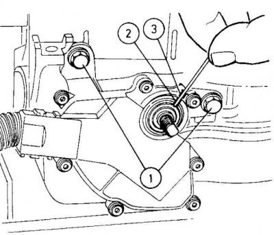
1. Switch bolts
2. Slots
3. Rod
Removal
1. Place the gearshift lever in neutral (N). Raise and support the front of the vehicle.
2. Remove the bolts securing the front section of the exhaust pipe and the catalytic converter to the intermediate pipe.
3. Remove the heat shields to gain access to the driveshaft center bearing.
4. Remove the two bolts securing the bearing to the body.
5. Disconnect the switch wire from the connector. Disconnect the connector from the transmission.
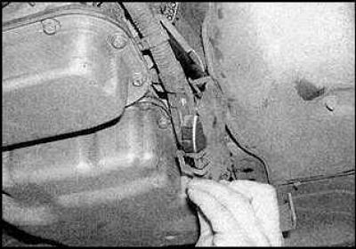
6. Remove the switch cover.
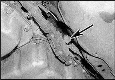
7. Tighten the locknut (indicated by the arrow) and disconnect the gearshift lever from the shift rod.
8. Place a jack under the gearbox and lift it slightly.
9. Remove the bolts securing the rear crossmember of the gearbox to the body.
10. Lower the transmission slightly to access the shifter bolts.
11. Remove the bolts and remove the switch.
Installation
1. Check that the gearshift rod is in position (N).
2. Install the new switch onto the switch shaft and tighten the bolts.
3. Adjust the switch.
4. Connect the shift rod to the shift lever and tighten the lock nut.
5. Connect the wire to the connector.
6. Secure the connector.
7. Tighten the crossmember bolts.
8. Install the remaining parts.
Adjustment
1. Place the gearshift lever in neutral (N). Raise and support the front of the vehicle.
2. Remove the cover from the shifter, loosen the lock nut and disconnect the transmission shift lever from the shift rod.
3. In the neutral position, the slot in the switch housing should align with the slot on the inner ring of the switch (see figure Adjusting the switch).
Gearbox sport mode switch
Removal
1. Remove the gear shift boot.
2. Remove the switch from the top of the lever.
3. Unsolder the wires from the switch.
4. Label the contacts and their corresponding wires.
Installation
1. Solder the wires to the switch contacts.
2. Set the switch.
3. Install the lever cover.
Winter mode switch for gearbox
Removal
1. Remove the gear shift boot.
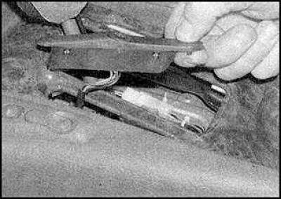
2. Remove the switch panel.
Installation
Installation is carried out in the reverse order of removal.
Downshift mechanism switch
Removal and installation
The switch is connected to the accelerator cable and cannot be removed separately.
Shift Lever Lock Switch - Late Models
Removal
1. Remove the center portion of the instrument panel.
2. Remove the front and rear heater rear vent brackets and remove the duct.
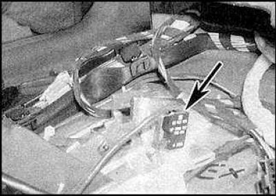
3. Disconnect the wires and remove the switch (indicated by the arrow) from the gear shift lever support plate.
Installation
Installation is carried out in the reverse order of removal.
Shift Lever Lock Solenoid - Late Models
Removal
1. Remove the gear shift lever.
2. Disconnect the solenoid ground from the lever base plate and disconnect the switch wire from the connector.
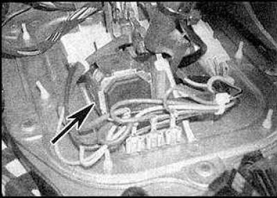
3. Remove the screws and take off the solenoid (indicated by the arrow).
Installation
Installation is carried out in the reverse order of removal.
Ignition Lock Switch - Early Models
Removal
1. Remove the center portion of the instrument panel.
2. Remove the front and rear heater rear vent brackets and remove the duct.
3. Disconnect the shift lever wire and the switch wire. Disconnect the switch ground wire from the shift lever bracket.
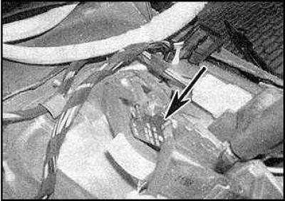
4. Remove the switch (indicated by the arrow).
Installation
Installation is carried out in the reverse order of removal.
Electronic control unit (ECU)
Removal
1. Disconnect the negative battery cable.
2. Remove the glove box.
3. Unscrew the nuts and remove the ECU. Disconnect the unit wires.
Installation
1. Installation is carried out in the reverse order of removal.
2. If you are installing a new unit, please contact a specialist.
Gearbox driven shaft sensor
Removal
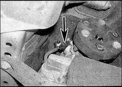
1. Sensor (indicated by the arrow) installed at the rear of the gearbox.
2. Raise and support the front of the vehicle.
3. Disconnect the sensor wire.
4. Unscrew the bolt and remove the sensor.
Installation
Installation is carried out in the reverse order of removal.
Gearbox electromagnetic valves
Removal and installation
Leave the work of removing and installing valves to a specialist.
Visitor comments