
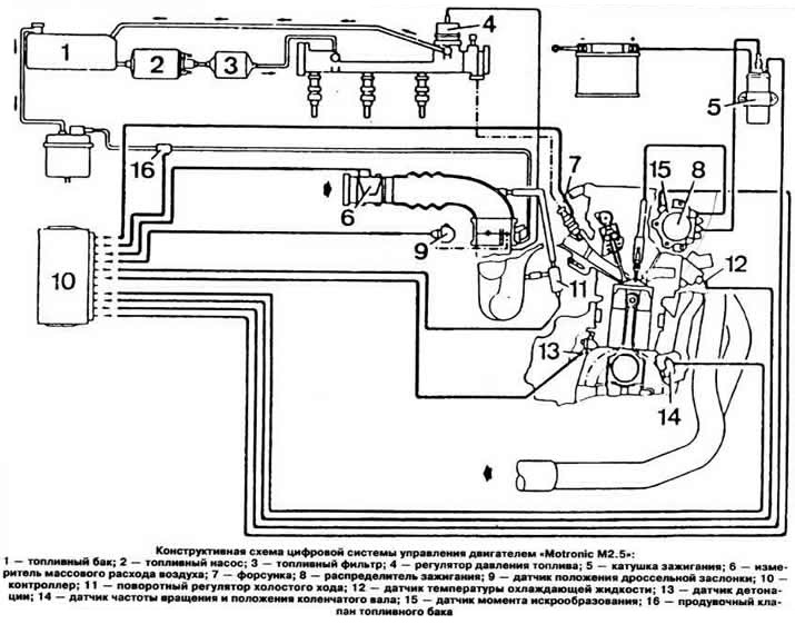
- a thermo-anemometric air mass flow meter is used, which provides measurement of the intake air volume, regardless of atmospheric pressure and air temperature. Air entering the engine flows around a thin platinum filament mounted in the meter. The filament is part of a bridge circuit whose diagonal voltage is adjusted to zero by varying the heating current. The heating temperature of the thread is maintained constant by means of an electronic control circuit. With an increase in the mass of air taken in, the filament current automatically increases accordingly, thereby maintaining a constant temperature of the filament. The glow current serves as a measure of the mass of air sucked in by the engine. The parameter that determines the mass flow rate of air entering the engine is the voltage required to maintain a constant temperature of the filament. For 1 second after each stop of the engine, the filament is heated to a very high temperature at the command of the controller to remove contaminants that could distort the output signal.
- system «Motronic M2.5» works according to the cylinder selection principle, i.e. the timing and duration of fuel injection, the timing of ignition and its change to prevent detonation are calculated separately for each cylinder. For this reason, for this system, in addition to the signal from the speed and crankshaft position sensor, the TDC signal of the compression stroke of cylinder No. 1 is required. This signal is sent to the controller from the spark moment sensor, which works on the principle of a Hall sensor installed in the ignition distributor;
- the fuel pressure regulator is built into the distribution line and cannot be removed separately;
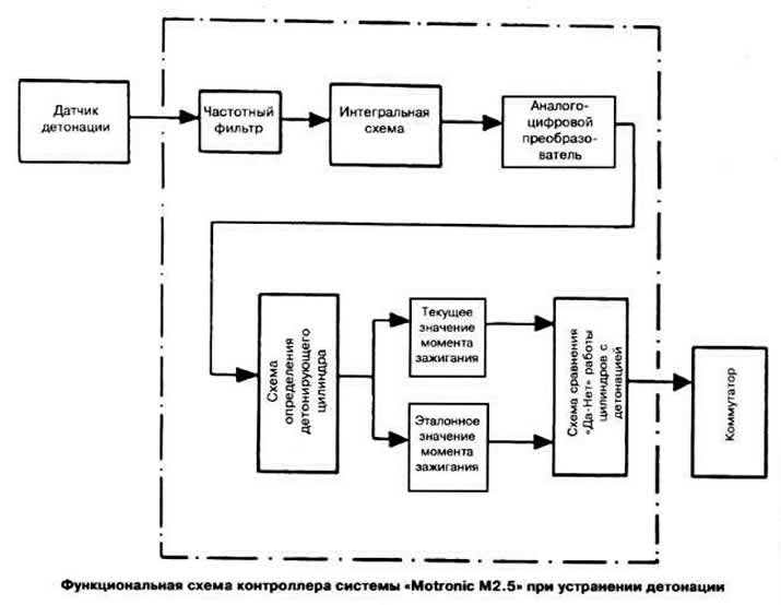
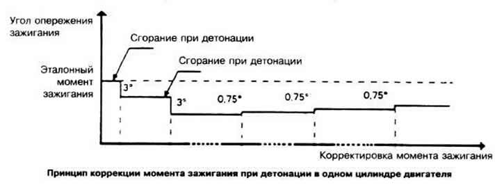
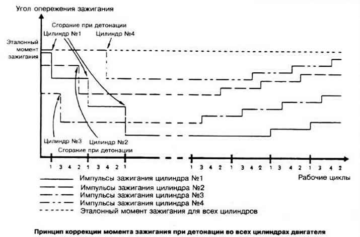
- a knock sensor is installed on the cylinder block, which perceives changes in the noise of the engine (detonation pops) and giving corresponding signals to the controller. The signal from the knock sensor passes at the input of the controller through a partial filter at 14 kHz and enters the integrating circuit, provided that it corresponds to the ignition timing, which is within 10-60°after TDC. The signal is then digitized by an analog-to-digital converter and compared with the average reference value over the last 16 cycles of the given cylinder. If the received signal is greater than the average reference value, this serves as the basis for the controller to change the ignition timing. If the received signal is less than the average reference value, it becomes the new ignition timing reference for that cylinder. If the ignition timing needs to be corrected, the controller advances the ignition timing for the next cycle of that cylinder by 3°retarded and again by 3°for the next cycle if the correction is insufficient. If during 20-120 ignitions of the mixture, which take about 2 seconds, the ignition timing is shifted each time by 0.75°towards the advance, until it reaches the reference value or detonation appears again;
- regulation of the ignition angle according to the detonation limit ensures automatic adaptation of the engine operation to the octane number of the fuel. The controller's memory contains two programs for controlling the ignition timing depending on the octane number of the fuel used. One of them is designed for gasoline with an octane rating of 95 and is activated after 50 combustions with detonation. The transition to another program, provided for the operation of the engine on gasoline with an octane rating of 98, occurs if the engine has been running for 8.5 minutes without detonation;
- system «Motronic M2.5» is a sequential phased fuel injection system. The injectors are controlled separately for each cylinder. In this case, fuel is supplied only to the cylinder that operates in the suction stroke;
- the crankshaft speed and position sensor is mounted on the engine block opposite the gear rim mounted on the engine crankshaft. It generates a voltage pulse when a toothed rim passes through its magnetic field. As the teeth of the rim pass in front of the magnetic sensor, the air gap between the rim and the sensor changes. The changing leakage flux induces a sinusoidal alternating voltage in the sensor winding, the amplitude of which depends on the peripheral speed of the gear rim, the air gap between the rim tooth and the sensor, the shape of the teeth, the magnetic characteristics of the sensor and the mounting bracket. Depending on the speed of the engine crankshaft, the controller receives voltage pulses of 0.5-100 V from the sensor, which are converted by the input stage of the controller each time the counting circuit is set to zero into rectangular voltage pulses of constant amplitude necessary for the operation of subsequent controller circuits. The angular gap between the teeth of the rim is 6°. The rim is missing two teeth. When a toothless section of the rim passes in front of the sensor, which serves as a marker, the controller receives a pulse of the initial position of the crankshaft. If the engine does not start or starts with difficulty, then the cause of this may be a malfunction of this sensor.
Visitor comments