


Contents: Checking and adjusting engine idle…⬇ Checking fuel pressure ⬇ Checking the mass air flow meter ⬇ Checking the CO correction…⬇
The procedure for performing most of the checks and adjustments of the components of the fuel injection system of the "Motronic M2.5" system is similar to those described above for the system "Motronic ML4.1". Below is a description of those checks and adjustments, the implementation of which has its own specific features.
Checking and adjusting engine idle speed
Adjustment of the carbon monoxide (CO) content in the exhaust gases can be carried out as described for the system "Motronic ML4.1", or by proceeding as follows:
- make sure the ignition is off;
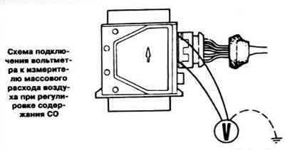
- connect a digital voltmeter to terminals "2" and "6" (see picture) air flow meter pads without disconnecting the connector;
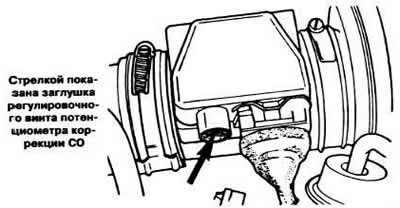
- connect the gas analyzer according to the operating instructions, start the engine at idle speed and check the CO content, which should be within 0.7-1.2%. If it differs from the norm, remove the plug of the adjusting screw (shown by the arrow in the figure) correction potentiometer CO and turn the screw until a voltage of 0.9-1.4 V is obtained on the voltmeter;
- press the accelerator pedal several times and let the engine idle: the level of CO in the exhaust gases should be within the required limits;
- after adjustment, install a new plug on the adjustment screw of the CO correction potentiometer.
Checking fuel pressure
Slowly unscrew the fitting securing the fuel supply line to the fuel line to gradually release the pressure.
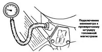
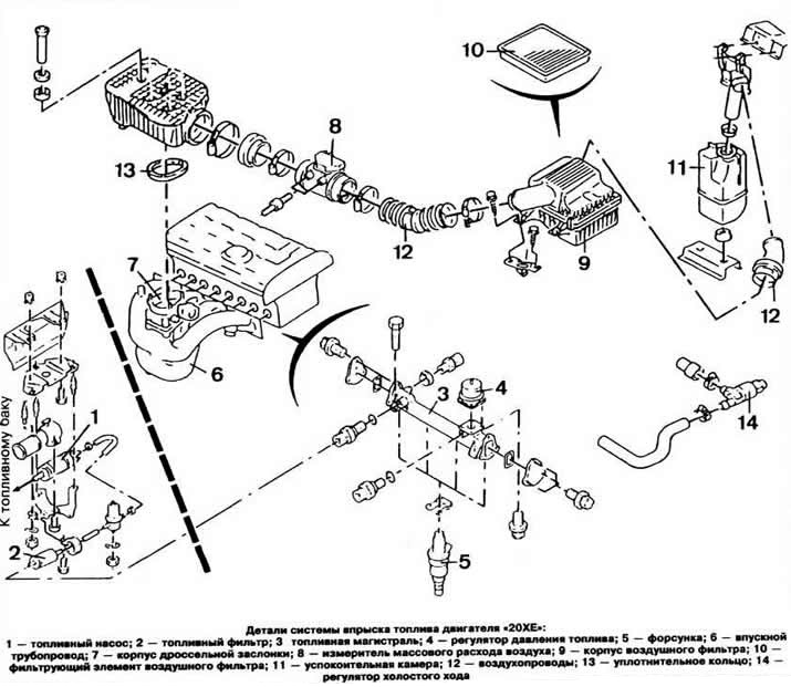
Attach a pressure gauge to the fuel line test nipple (see picture).
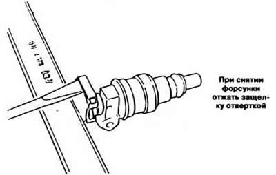
Disconnect the vacuum hose from the pressure regulator.
Start the engine at idle speed.
Measure the fuel pressure in the system using a pressure gauge; it should be within 2.3-2.7 kg/cm².
Connect the vacuum hose to the pressure regulator, after which the fuel pressure should decrease by 0.3-0.5 kg/cm².
Turn off the ignition, disconnect the pressure gauge.
Connect the pressure gauge through a tee to the fuel drain hose and disconnect the vacuum hose from the pressure regulator. The pressure gauge should show a pressure of 0.3-0.5 kg/cm². Adjusting the position of the throttle position sensor
Remove the protective cover from the throttle body.
Loosen the clamp securing the mass air flow meter, unscrew the five screws securing the meter and remove the meter.
Disconnect the wire harness connector.
Remove the two mounting clamps and unscrew the two nuts on the bracket.
Loosen the two Phillips head screws and turn the throttle position sensor housing counterclockwise to remove clearance, then turn the sensor housing clockwise until resistance is felt. Tighten the two Phillips head screws securing the sensor housing.
To check the operation of the sensor, open the throttle valve slightly and you should hear the switch click.
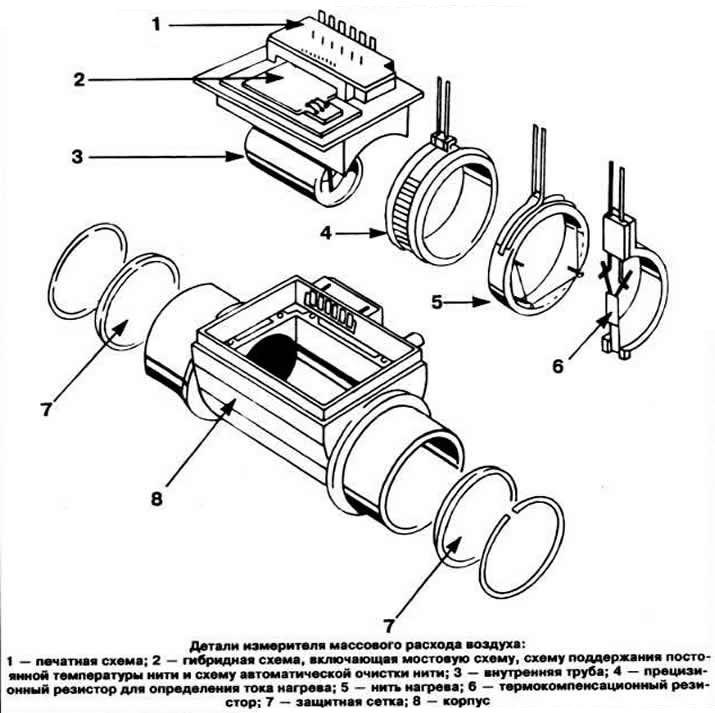
Checking the mass air flow meter
Disconnect the measuring connector and connect the ohmmeter to terminals "1" and "2" of the block and measure the resistance, which should be zero.
Connect the ohmmeter to terminals "2" and "3" of the meter block. The resistance on the ohmmeter should be within 2.5-3.1 Ohms.
Disconnect the clamp securing the air duct to the meter.
Remove the gauge holder.
Start the engine and let it run for 10 seconds at a crankshaft speed of about 1000 rpm.
Turn off the ignition, remove the air duct and check the condition of the filament of the meter, which should be bright red for about 1.5 seconds after 4 seconds of stopping the engine.
Checking the CO correction potentiometer
Slide the insulating boot off the mass air flow meter connector.
Connect a digital voltmeter to terminals "2" and "6" of the connector.
Start the engine at idle speed. The voltage on the voltmeter should be within 0.9-1.4 V.
Turn off the ignition. Connect the ohmmeter to terminals "2" and "6" of the meter block.
Remove the potentiometer adjustment screw cap.
Mark the position of the potentiometer adjustment screw and turn it fully counterclockwise. The resistance on the ohmmeter should be within 0-30 Ohms.
Turn the potentiometer screw clockwise until it stops. The resistance on the ohmmeter should be within 900-1100 Ohms.
Turn the potentiometer adjustment screw to the previously marked position.
Note: Do not change the factory throttle setting under any circumstances. Before removing the idle speed control valve, mark the air hoses so that they can be reattached to their original locations during installation.
Visitor comments