
In order not to damage circuits and system elements, always disconnect the connector for connecting the electronic control unit before carrying out repairs.
Hydraulic modulator, early models with 3-channel 2-SH or 2-SH/TC ABS
Removing
1. Disconnect the negative battery cable.
2. Remove the cap from the brake fluid reservoir and cover the filler neck with plastic wrap.
3. Remove the power steering reservoir. Remove the ABS electronic control unit.
Models with 4-cylinder engine
4. Disconnect the hydraulic pipes from the modulator. Loosen the fixing screws and remove the heat shield.
Models with 6-cylinder engine
5. Disconnect the upper hydraulic tubes from the modulator. Loosen the fixing screws and remove the heat shield.
6. Disconnect the lower hydraulic tubes.
All models
7. Disconnect the ground wire, unscrew the fixing nuts and remove the modulator.
Installation
Installation is carried out in the reverse order of removal.
Hydraulic modulator and electronic control unit for ABS / traction control, later models with 4-channel ABS 5.3 or 5.3 / TC
Removing
1. Disconnect the negative battery cable.
2. Remove the protective shield from the bottom of the engine compartment.
3. Remove the heat shield from the side of the hydraulic modulator.
4. Remove the power steering reservoir.
5. Loosen the fixing screw and disconnect the connector for connecting the ABS electronic control unit.
6. Disconnect the brake pipes from the master brake cylinder.
7. Unscrew the connection nuts and disconnect the six hydraulic tubes from the modulator.
8. Remove the modulator from the mounting bracket.
Installation
Installation is carried out in the reverse order of removal.
ABS/traction control ECM, early models with 3-channel 2-SH or 2-SH/TC ABS
Removing
Remove the casing of the electronic control unit, disconnect the connection connector, unscrew the fixing bolts and remove the unit.
Installation
Installation is carried out in the reverse order of removal.
Traction control switch.
Removing
1. Pry off the switch with a small screwdriver and remove it from the instrument panel.
2. Disconnect the switch connector.
Installation
Installation is carried out in the reverse order of removal.
Front wheel ABS sensors
Removing
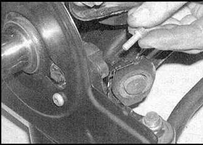
1. Disconnect the connection connector, unscrew the fixing bolt.
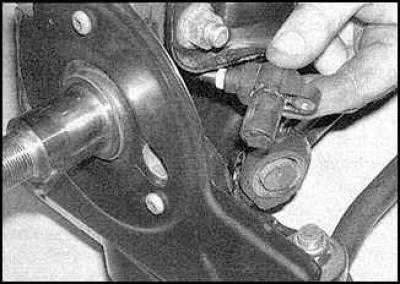
2. Remove the sensor from the mounting bracket.
Installation
Installation is carried out in the reverse order of removal.
Rear wheel ABS sensors
Removing
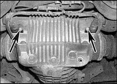
1. Disconnect the connection connector, unscrew the fixing bolt and remove the sensors (indicated by arrows) from the differential.
Installation
Installation is carried out in the reverse order of removal.
Visitor comments