


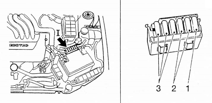
The Vectra has up to 6 input fuses. As can be seen in the illustration on the left, they are located in the engine compartment behind the battery: in the fuse holder. On the right, the numbers indicate:
1 - Engine control input fuse;
2 - Secondary air boost and ABS input fuse;
3 - Input fuse of the positive battery terminal of the instrument panel wiring harness.
In order that the Vectra would not be completely de-energized in the event of a fault, the fuses are distributed among different electrical circuits. However, the connections between the starter, battery and generator are not protected by fuses. If these parts fail, a glance at the fuse box will not help. However, the remaining electrical units have their own interlock. The Vectra uses so-called plug-in fuses with flat connectors. Two flat connectors are inserted into a painted synthetic part, connected by a fusible wire. With such fuses, there are no problems with corrosion, since they have larger contact surfaces than the old ceramic fuses.
Main fuses
Up to 6 main fuses protect a number of electrical circuits. These main fuses eliminate the risk of fire in permanently live wires. The main fuses are located in a fuse holder divided into three parts, which is located in the engine compartment behind the battery. After the main fuses, the current flows to individual fuses in the car and from them to electrical consumers. If one of these fuses burns out, it is imperative to find out the cause of the short circuit. A temporary jumper of the main fuse can lead to a fire in the wires.
Replacing the fuse
If you need to replace a plug fuse, you can use the small plastic pliers that are attached to the fuse box.
If the new fuse blows immediately, check to see if the fuse is too small (see fuse table).
If this is not the case, then use the fuse table to determine the connected power consumer and check it separately. The corresponding electrical diagram will help with this (next chapter).
In case of doubt, disconnect all consumers and then connect them one by one. The consumer whose fuse blows when connected is faulty.
Power of fuses
To distinguish the maximum permissible rated current (amperes), the identification colors of the synthetic part are used: red - 10 A; blue - 15 A; yellow - 20 A; white - 25 A; green - 30 A; orange - 40 A.
Visitor comments