
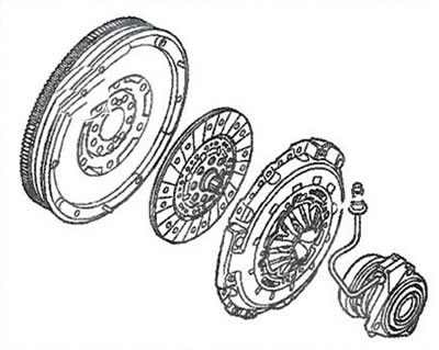
Power is transferred from the flywheel on the engine to the transmission input shaft via the clutch disc. Power transmission is possible thanks to the pressure plate, which is bolted to the flywheel and presses the friction surfaces of the clutch disc against the flywheel.
The clutch driven disk is mounted on the input shaft of the gearbox on splines. When the slave cylinder release bearing presses on the diaphragm spring petals, they, like levers, remove the pressure plate clamping force from the clutch disc and flywheel, due to which the engine is disconnected from the transmission.
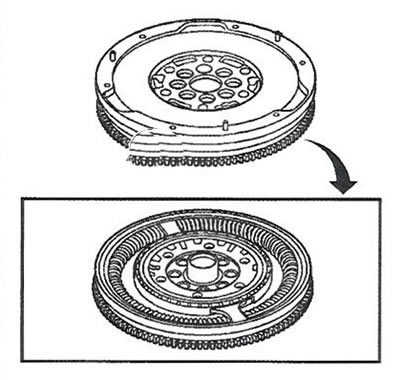
Dual mass flywheel (DVA) has one mass connected directly to the crankshaft, and the other to the input shaft of the gearbox, interconnected by an elastic system that dampens torsional vibrations.
Resonance point in a conventional circuit (one-piece flywheel and clutch disc with damper springs), between 800 and 2200 rpm, is shifted to a lower speed outside the operating range, resulting in a significant reduction in noise and vibration.
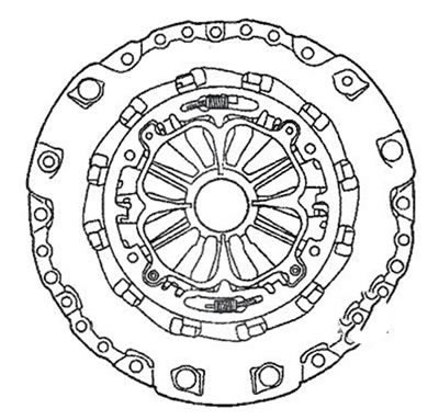
The clutch pressure plate is fully self-adjusting, so that the pressure springs under the influence of the release bearing always ensure an even distribution of the pressing force relative to the release bearing. The diaphragm spring has the ability to move between the adjusting and compensation rings.
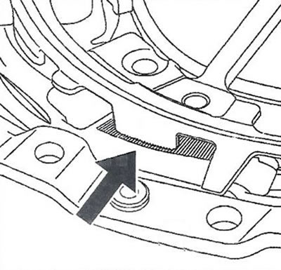
As the friction linings of the clutch disc wear, the wear ring moves with the pressing surface of the pressure plate. This movement relieves the load on the adjusting ring, which is rotated by two small springs and is fixed in position by a hook in the pressure plate housing, due to which the diaphragm spring is set in the desired position.
When replacing the dual-mass flywheel, it is also necessary to replace the clutch pressure and working discs in one set.
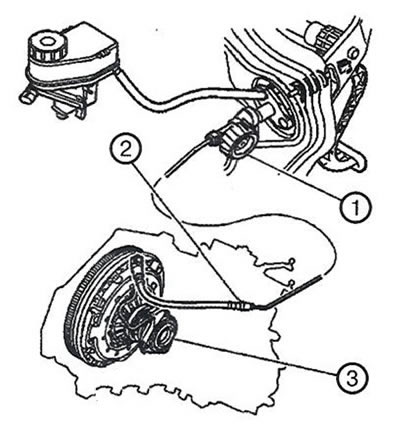
1. Clutch master cylinder.
2. Connecting line.
3. Clutch slave cylinder.
The hydraulic clutch drive is also fully self-adjusting. Clutch hydraulic components are shown in the illustration.
The clutch master cylinder is mounted on a bulkhead and connected to the clutch pedal via a rod.
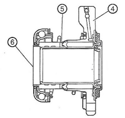
4. Cylinder body.
5. Composite piston.
6. Fixed release bearing.
The clutch slave cylinder is a block built into the clutch basket. Clutch slave cylinder components are shown in the illustration.
The clutch slave cylinder is not collapsible. Hydraulic pressure from the master cylinder is transferred to the seal, which then pushes the piston with the release bearing against the pressure plate. A spring is installed between the cylinder body and the release bearing, so that the release disk is always pressed against the pressure disk, which reduces the play of the clutch pedal.
The hydraulic line connecting the master and slave cylinders of the clutch is a damper pipeline (to reduce pedal vibration) and has quick-release connectors on both sides. The lower quick-release connector on the side of the working cylinder is equipped with a fitting for pumping the hydraulic drive.
Visitor comments