
Removing
1. Open the hood.
2. Disconnect the negative battery terminal.
3. Remove the engine cover.
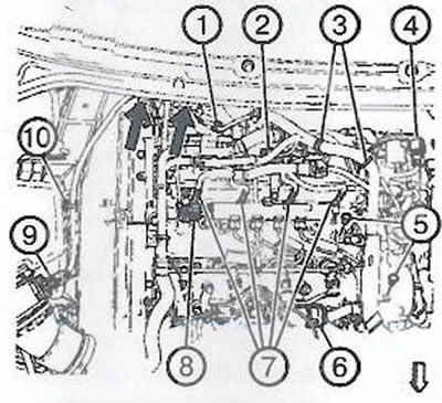
4. Remove two screws (5).
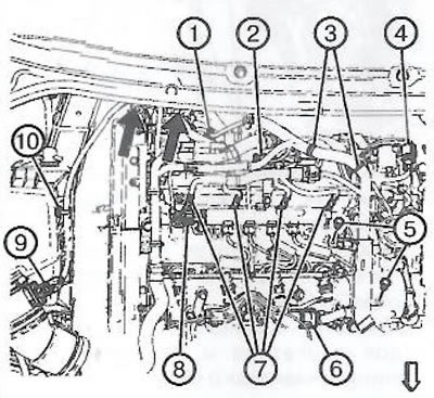
5. Disconnect the following connectors:
- throttle body (4);
- four glow plugs (7);
- intake manifold pressure sensor (2);
- high pressure fuel pump (1);
- fuel rail (8);
- mass air flow sensor (9).
6. Remove the harness holders (10 pieces.) from the air filter assembly and from the bracket (shown by arrows in the figure).
7. Take the wiring harness to the side.
8. Remove the camshaft housing.
9. Remove the EGR valve heat exchanger.
10. Remove catalytic converter.
11. Remove the turbocharger.
12. Remove the oil dipstick tube.
13. To remove the pipeline of system of compulsory ventilation of the fulfilled gases.
14. Remove the radiator outlet hose.
15. Remove fuel return hose.
16. Install support CH-49290, following the manufacturer's instructions.
17. Remove the timing belt.
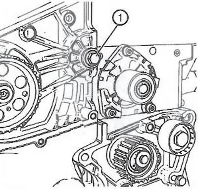
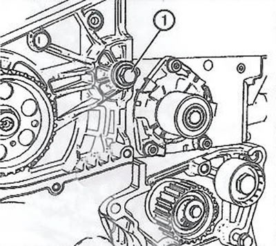
18. Loosen the bolt (1) high pressure fuel pump bracket.
19. Unscrew the upper bolt of the oil separator of the forced exhaust ventilation system.
20. Raise and secure the car.
21. Remove the coolant outlet hose from the oil cooler.
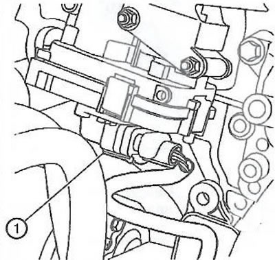
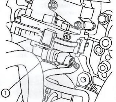
22. Disconnect the wire connector (1) collector drive.
23. Lower the car.
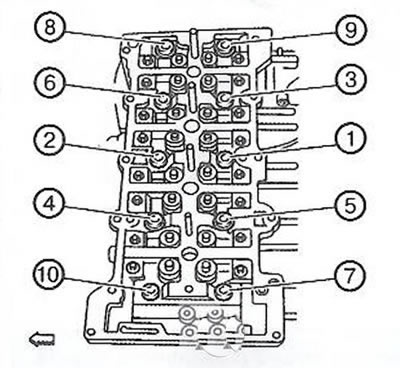
24. Loosen the 10 cylinder head bolts in the sequence shown in the figure as follows:
- Loosen the cylinder head bolts by 90° (quarter turn).
- Loosen cylinder head bolts another 180° (half a turn).
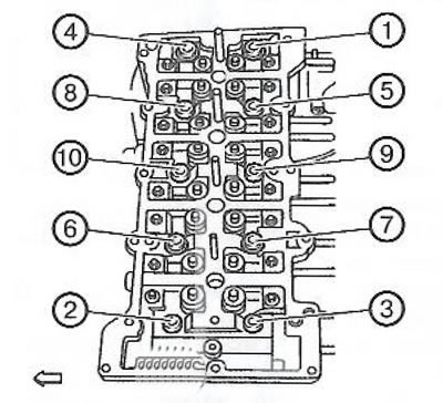
25. Completely remove and discard the 10 cylinder head bolts (2), then remove the cylinder head (3).
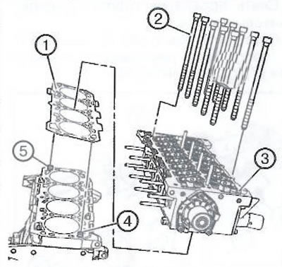
Attention. Be careful not to damage the guide pins (4) And (5).
26. Remove gasket (1) cylinder heads.
27. Remove the following parts from the cylinder head:
- Intake manifold,
- An exhaust manifold.
- Rocker arms and pushers with hydraulic compensators.
- Water pump.
28. Loosen the bolt (2) and remove bracket (1).
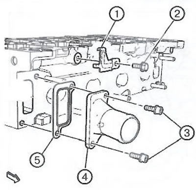
29. Remove the mounting bolts (3) and remove the outlet of the cooling system (4) with gasket (5).
Installation
Attention. Remove all debris from the threaded holes of the cylinder head bolts. Failure to do so may result in damaged threads, undertightening of threaded connections, or damage to components.
Note.
- Do not use old cylinder head bolts.
- Do not use any sealants or additional seals other than the cylinder head gasket provided.
- The cylinder head gasket must be installed in the correct direction.
1. Clean the contact surfaces and remove all dirt and remnants of the old gasket from the threaded holes, channels of the lubrication and cooling systems.
2. Check the flatness of the surface of the cylinder block and block head using a steel straight edge and a set of flat feelers.
3. Install the outlet of the cooling system (4) with new gasket (5).
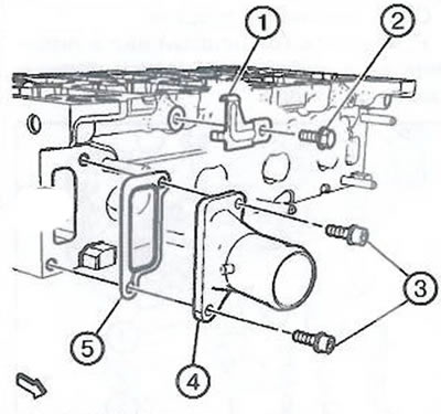
4. Install bolts (3) and tighten to 9 Nm.
5. Install bracket (1).
6. Install bolt (2) bracket and tighten to 9 Nm.
7. Install the following parts of the cylinder head:
- Intake manifold.
- An exhaust manifold.
- Roller rockers and pushers with hydraulic compensators.
- Water pump.
8. Check the correct thickness of the new cylinder head gasket (1) according to the marks shown in the figure:
- without hole: 0.95mm;
- single hole: 1.05mm;
- with two holes: 1.15 mm.
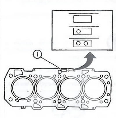
Note. Always install a new cylinder head gasket of the same thickness as before disassembly.
9. Install a new cylinder head gasket (1). side labeled «Thor» should be directed upwards.
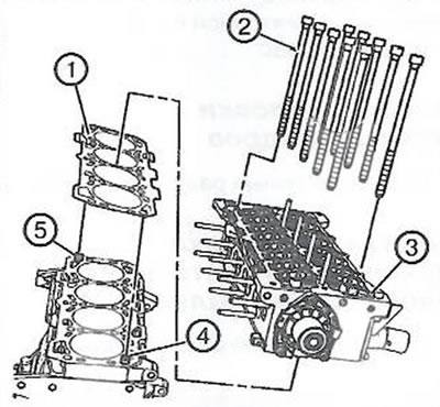
10. Install the cylinder head (3).
Note. Be careful not to damage the guide pins (4) And (5), and do not confuse the guide pins of the cylinder block with the guide pins of the camshaft housing.
11. Install 10 new cylinder head bolts (2).
12. Tighten 10 new cylinder head bolts in the sequence shown in the figure as follows:
A) Hex head bolts:
- First step: tighten to 20 Nm.
- Second step: tighten to 65 Nm.
- Step 3: Using tool EN 45059, tighten by 90°.
- Fourth step: Using tool EN 45059, tighten by 90°.
- Step 5: Tighten by 90°using tool EN 45059.
IN) Bolts Torx T60:
- First step: tighten the bolts to 20 Nm.
- Second step: tighten the bolts to 65 Nm.
- Step 3: Using tool EN 45059, tighten by 90°.
- Fourth step: Using tool EN 45059, tighten by 90°.
- Step 5: Tighten by 90°using tool EN 45059.
- Sixth step: Using tool EN 45059, tighten by 90°.
13. Raise the car.
14. Install the coolant outlet hose from the oil cooler.
15. Connect the electrical connector (1) collector drive.
16. Lower the car.
17. Install the upper crankcase ventilation oil separator bolt and tighten to 9 Nm.
18. Install bolt (1) high pressure fuel pump bracket and tighten to 25 Nm.
19. Install the timing belt.
20. Remove support CH-49290.
21. Install the fuel return hose.
22. Install the radiator outlet hose.
23. Install the pipeline of the forced crankcase ventilation system.
24. Install the oil dipstick fitting.
25. Install turbocharger.
26. Install the EGR valve cooler.
27. Install the camshaft housing.
28. Install the wiring harness and connect the following connectors:
- throttle body (4);
- glow plugs (7);
- manifold pressure sensor (2);
- high pressure fuel pump (1);
- fuel rail (8);
- mass air flow sensor (9).
29. Install 2 bolts (5).
30. Install holders (10) to the air filter assembly and bracket (shown by arrows in the figure).
31. Install the engine cover.
32. Connect the negative battery terminal.
33. Close the hood.
Visitor comments