


Measuring the axial clearance of the crankshaft
1. Install a dial indicator on the end of the crankshaft.
2. Carefully move the crankshaft back and forth in the longitudinal direction, measuring the axial play with a dial indicator.
3. The value of the crankshaft axial clearance must not exceed the specified value (see section "Service data and specification" at the end of the chapter).
4. If the obtained value of axial clearance exceeds the permissible norm, check the thrust half rings and adjacent surfaces of the crankshaft for wear and/or excessive runout.
5. Replace the thrust washers or crankshaft.
Removal
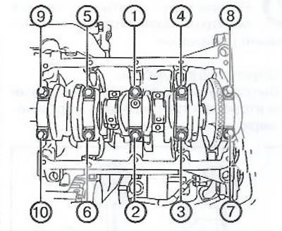
1. Loosen the crankshaft main bearing cap bolts in the sequence shown in the figure.
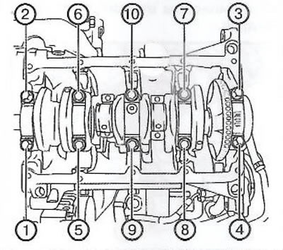
2. Completely unscrew the 10 crankshaft main bearing cap bolts (1, 2).
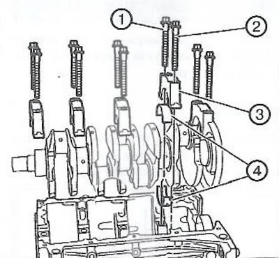
3. Remove 5 crankshaft main bearing caps (3).
4. Using both hands, pull the crankshaft upwards from the cylinder block.
5. Place the crankshaft on wooden blocks.
6. Prepare a sheet of cardboard or similar material numbered 1 through 5 to identify the main bearing shells. The shell numbering starts from the front of the engine.
7. Remove 10 main bearing shells (4) from the cylinder block and main bearing caps. Mark the position of the thrust half rings.
8. Place the main bearing shells on the prepared numbered sheet in the appropriate order.
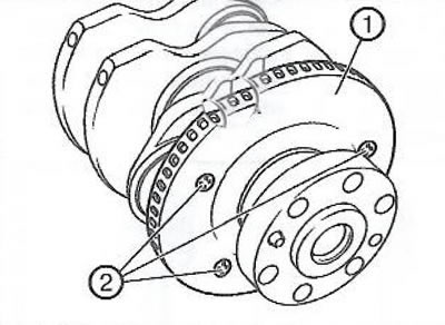
9. Loosen the three bolts (2) and remove the pulse disk (1) of the crankshaft speed sensor.
Installation
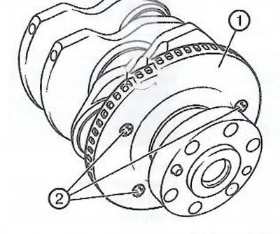
1. Install the crankshaft speed sensor pulse disk (1) and tighten the mounting bolts (2) to a torque of 12 Nm.
Original posted on the website OPELBOOK
2. Clean all surfaces of the crankcase with a lint-free cloth.
Note: If the crown bearing shells were used on an engine that has run away, they must be replaced with new ones.
3. Remove all traces of oil from the back of the new bearing shells.
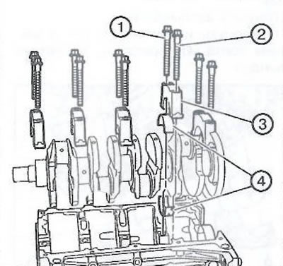
4. Install the 10 bearing shells (4) in their places. Make sure that the upper shells have oil holes and grooves. Insert the shells so that their locking lug coincides with the groove in the seat. The main bearing shells must be installed flush with the surface of the cylinder block.
5. Using both hands, install the crankshaft into the cylinder block.
6. Install five main bearing caps (3).
7. Install 10 new crankshaft main bearing cap bolts (1, 2).
8. Tighten the crankshaft main bearing cap bolts in the sequence shown in the figure in two stages:
- First step: tighten to 25 Nm.
- Step 2: Using the EN-45059 tool, tighten the bolts by another 100°.
Visitor comments