


Contents: Removal ⬇ Installation ⬇
Removal
1. Open the hood.
2. Remove the cylinder head.
3. Install the engine mounting bracket.
4. Install the engine mounting support.
5. Remove the oil pan.
6. Set the crankshaft to the top dead center position of the piston of the first cylinder.
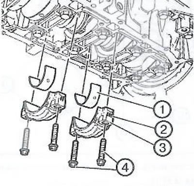
7. Loosen and discard the 4 connecting rod bolts (4) from the second and third cylinders,
8. Remove the connecting rod caps (3) from the second and third cylinders.
Note.
- Mark the connecting rod caps (2) for correct installation later.
- The connecting rod and cap joint surfaces are uniquely shaped to fit in one position, so the connecting rods and caps must not fall. Do not treat the joint surfaces.
9. Remove the lower connecting rod bearings (1).
Note: Arrange the removed parts in order according to the cylinder numbering.
10. Lower the vehicle.
11. Push the two pistons with connecting rods (1) out of the second and third cylinders through the top.
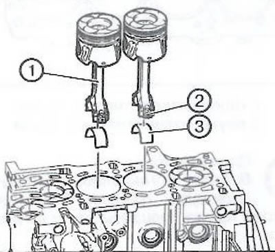
Note: Mark the connecting rods (2) and arrange them in order according to the cylinder numbering.
Caution: Be careful not to damage the cylinder bore surface, piston rings and piston surfaces.
12. Remove the two upper connecting rod bearings (3) of the connecting rods of the second and third cylinders.
13. Turn the crankshaft 180° to set the piston of the second cylinder to the top dead center position.
14. Raise the car.
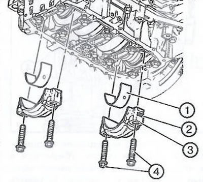
15. Loosen and discard the 4 connecting rod bolts (4) of the first and fourth cylinders.
Note
- Mark the connecting rod caps (2) for correct installation later.
- The connecting rod and cap joint surfaces are uniquely shaped to fit in one position, so the connecting rods and caps must not fall. Do not treat the joint surfaces.
16. Remove the connecting rod caps (3) of the first and fourth cylinders.
17. Remove the lower connecting rod bearings (1).
Note: Arrange the removed parts in order according to the cylinder numbering.
18. Lower the vehicle.
19. Push the two pistons with connecting rods (1) out of the second and third cylinders through the top.
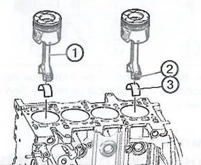
Note: Mark the connecting rods (2) and arrange them in order according to the cylinder numbering.
Caution: Be careful not to damage the cylinder bore surface, piston rings and piston surfaces.
20. Remove the two upper connecting rod bearings (3) of the connecting rods of the first and fourth cylinders.
Installation
1. Make sure that the piston ring locks are positioned as shown in the diagram (A, B, C).
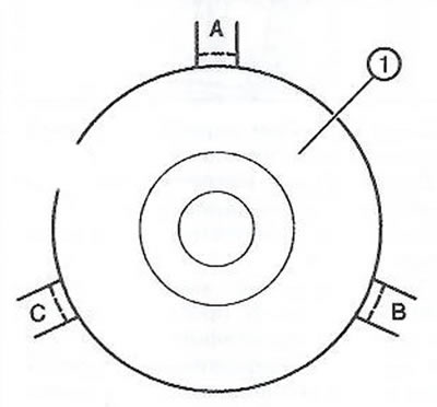
Note: The arrow on the piston bottom points towards the timing drive.
2. Lubricate the piston rings, pistons, cylinder bore and piston ring compressor with clean engine oil.
3. Install the piston ring compressor onto the pistons.
4. Insert the upper connecting rod bearings (1) into the connecting rods and insert the pistons with connecting rods as an assembly (1) into the first and fourth cylinders of the engine, using the previously applied marks (2) as a guide.
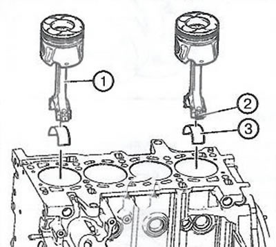
Caution: Be careful not to damage the cylinder bore surface, piston rings and piston surfaces.
5. Raise the car.
6. Insert the lower connecting rod bearings (1) and install the connecting rod caps (3) into the cylinders of the first and fourth cylinders.
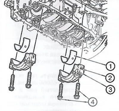
Caution: Be careful not to scratch or damage the connecting rod bearings.
7. Install 4 new connecting rod bolts (4) and tighten in two stages:
- First step: tighten to 25 Nm.
- Second step: tighten by another 60° using the EN-45059 device.
8. Turn the crankshaft 180° and set the crankshaft to the top dead center position of the piston of the second cylinder.
9. Lower the vehicle.
10. Insert the upper connecting rod bearings (1) into the connecting rods and insert the pistons with connecting rods as an assembly (1) into the second and third cylinders of the engine, using the previously applied marks (2) as a guide.
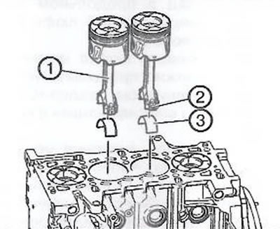
Caution: Be careful not to damage the cylinder bore surface, piston rings and piston surfaces.
11. Raise the car.
12. Insert the lower connecting rod bearings (1) and install the connecting rod caps (3) into the cylinders of the second and third cylinders.
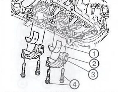
Caution: Be careful not to scratch or damage the connecting rod bearings.
13. Install 4 new connecting rod bolts (4) and tighten in two stages:
- First step: tighten to 25 Nm.
- Second step: tighten by another 60° using the EN-45059 device.
14. Turn the crankshaft in the direction of normal rotation to a position of 60° to the top dead center of the piston of the first cylinder.
15. Install the oil pan.
16. Install the SN-49290 device, following the manufacturer's instructions.
17. Remove the engine mounting support.
18. Remove the engine mounting bracket.
19. Install the cylinder head.
20. Close the hood.
Visitor comments