


Contents: Heating control module ⬇ Coolant temperature sensor ⬇ Fuel filter heating element ⬇ Fuel filter heating element…⬇ Relays and fuses ⬇
Heating control module
1.7L and 2.0L low-pressure turbocharged engines
The module is installed in the engine compartment, on the left side of the battery support bracket.
1. Disconnect the negative cable from the battery.
2. Lift the module up and off the battery support bracket.
3. Disconnect the electrical wiring from the base of the module and remove the latter from the engine compartment.
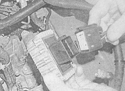
4. Installation is carried out in reverse order.
2.0L High-Pressure Turbocharged Engines
The operation of the system is controlled by the engine management system, the procedures for removing the system components are described in Chapter Power and exhaust systems.
Coolant temperature sensor
Cm. Checking the proper functioning, removal and installation of electrical components of the engine cooling system control circuit.
Fuel filter heating element
1. Before starting work, conduct marketing of the availability of the necessary spare parts for sale. Remove the fuel filter (see Chapter Routine maintenance), if damaged, replace.
2. Disconnect the negative cable from the battery, then disconnect the wiring from the heating element.
3. Unscrew the central bolt and remove the heating element from the filter housing - the sealing ring must be replaced without fail.
4. Place a new sealing ring on the heating element protrusion. Install the element onto the filter housing, screw in and tighten the mounting bolt securely.
5. Connect the negative cable to the battery. Install the filter in its regular place (see Chapter Routine maintenance).
Fuel filter heating element temperature sensor switch
1. Before starting work, conduct marketing of the availability of the necessary spare parts for sale. Disconnect the negative cable from the battery, then disconnect the wiring from the sensor-switch screwed into the fuel filter housing.
2. Place a drain container under the filter or lay a rag to collect spilled fuel. Unscrew the sensor-switch - immediately seal the hole for its installation with a suitable plug. Remove the sensor-switch sealing rings - the rings must be replaced during assembly.
3. Place new sealing rings into the grooves of the sensor-switch. Screw the sensor-switch into the fuel filter housing and tighten it securely. Restore the original wiring connection.
4. Connect the negative cable to the battery.
Relays and fuses
Removal and installation
The relays and fuses are located in the mounting block installed in the engine compartment - see Chapter On-board electrical equipment.
Examination
Checking with the relay disconnected
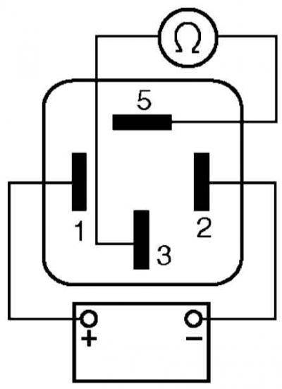
1. Remove the relay. Contacts 3 and 5 should be open when 12 V power is applied to terminals 1 () and 2 (-) of the relay - do not mix up the polarity of the power supply connection!
Checking with the relay connected
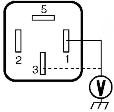
1. When the ignition is off, there should be a voltage of 11-14 V at terminal 3; when the ignition is on, the same voltage should be present at terminal 1.
Visitor comments