
2.0L DOHC engine
Fan and filter
1. Remove the left front wheel housing insert.
2. Remove the horn.
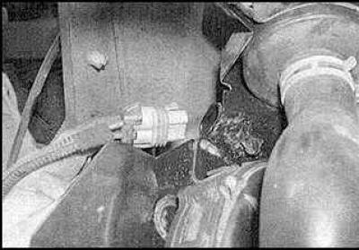
3. Disconnect the connector
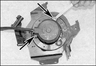
4. Loosen the clamp and disconnect the air hose from the fan.
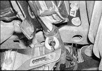
5. Loosen the fixing nuts (indicated by arrows) and remove the fan together with the bracket.
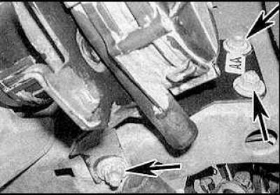
6. To remove the air filter, remove the clamp (A), disconnect the air hose from the fan, unscrew the fixing nut (IN) filter and remove the clip and filter.
7. Remove the fan connector.
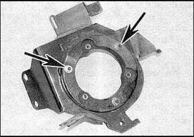
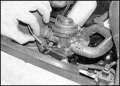
8. Loosen the fixing screws (indicated by arrows).
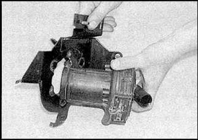
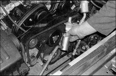
9. Remove the pump from the mounting bracket.
10. Loosen the fixing nuts if necessary (indicated by arrows) and remove the mounting plate.
11. Installation is carried out in the reverse order of removal.
Shut-off valve
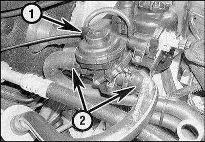
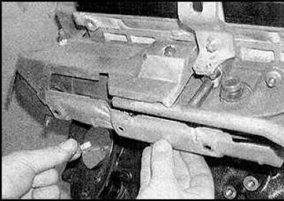
1. Disconnect the vacuum tube (1) and air hoses (2) from the valve.
2. Turn off fixing bolts and remove the valve.
3. Installation is carried out in the reverse order of removal.
Shut-off valve solenoid
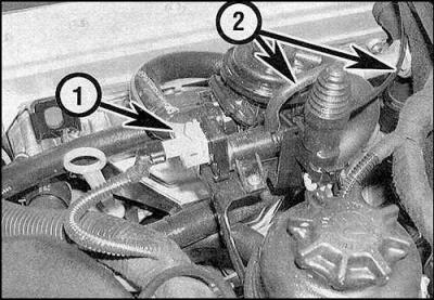
1. Disconnect the connector (1) and vacuum hoses (2) from the solenoid.
2. Loosen the mounting screws and remove the solenoid.
3. Installation is carried out in the reverse order of removal.
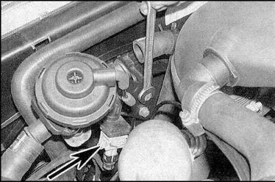
Stop valve
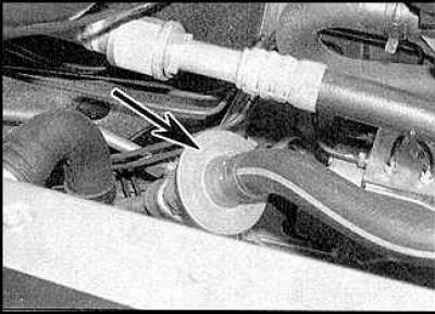
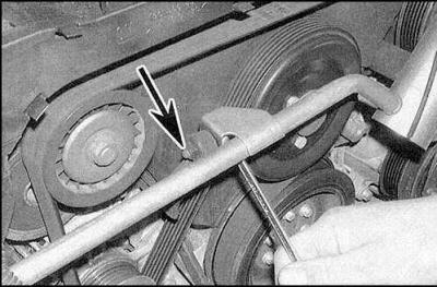
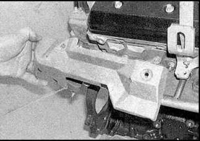
1. Disconnect the air hose and remove the valve (indicated by an arrow).
2. Use sealant when installing the valve.
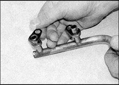
Connecting tube
1. Disconnect the air hose from the shutoff valve.
2. Loosen the mounting bolts and remove the tube mounting bracket.
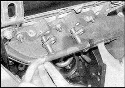
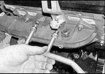
3. Disconnect the tube from the cylinder head cover, unscrew the fixing bolts and remove the tube.
4. Installation is carried out in the reverse order of removal.
2.5L and 3.0L engines
Fan and filter
See higher.
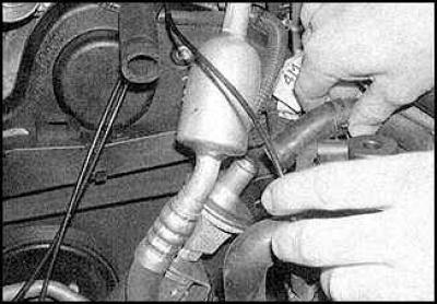
Shutoff valve and solenoid
1. Disconnect the vacuum tube from the solenoid.
2. Disconnect the air hoses from the valve.
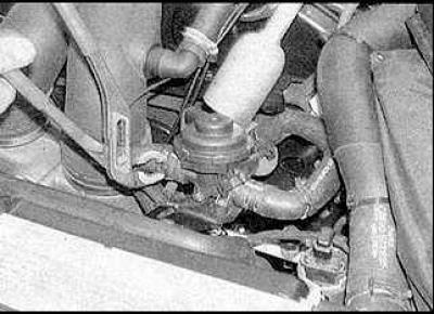
3. Loosen the mounting bolts and remove the valve mounting bracket. Disconnect the connector (indicated by an arrow).

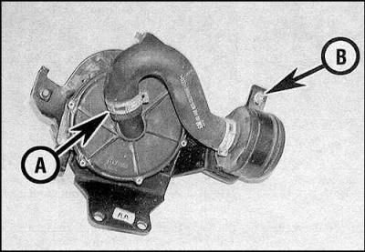
4. Unscrew the mounting bolts and remove the shut-off valve (A) or solenoid (IN) from the mounting bracket.
5. Installation is carried out in the reverse order of removal.
Stop valve
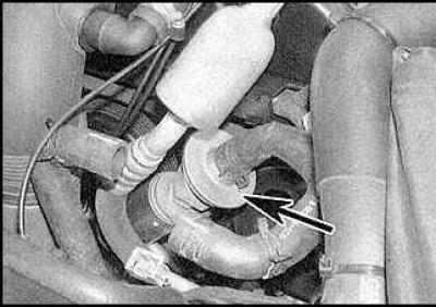
1. Disconnect the air hose and unscrew the valve (indicated by an arrow) from the tube.
2. Installation is carried out in the reverse order of removal.
Front connecting tube
1. Remove the pre-chamber of the air supply system.
2. Disconnect the air hose from the valve on the tube.
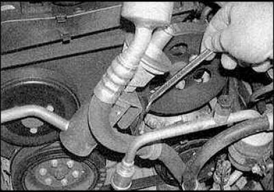
3. Loosen the fixing nuts on the left side.
4. Unscrew the fixing nuts on the right side, set aside the generator mounting bracket (indicated by an arrow), if it is needed.
5. Pick up the handset.
6. Installation is carried out in the reverse order of removal.
Connecting tube for left bank of cylinders
1. Remove a reception pipe of an exhaust system of the left number of cylinders.
2. Unscrew the fixing bolts and disconnect the tube from the manifold.
3. Installation is carried out in the reverse order of removal. Use new gaskets.
Connecting tube for the right number of cylinders
1. Unscrew the mounting bolts and remove the lower protective screen from the exhaust manifold.
2. Unscrew the mounting bolts and remove the upper protective screen from the exhaust manifold.
3. Unscrew the fixing bolts and disconnect the tube from the manifold.
4. Installation is carried out in the reverse order of removal. Use new gaskets.
Visitor comments