
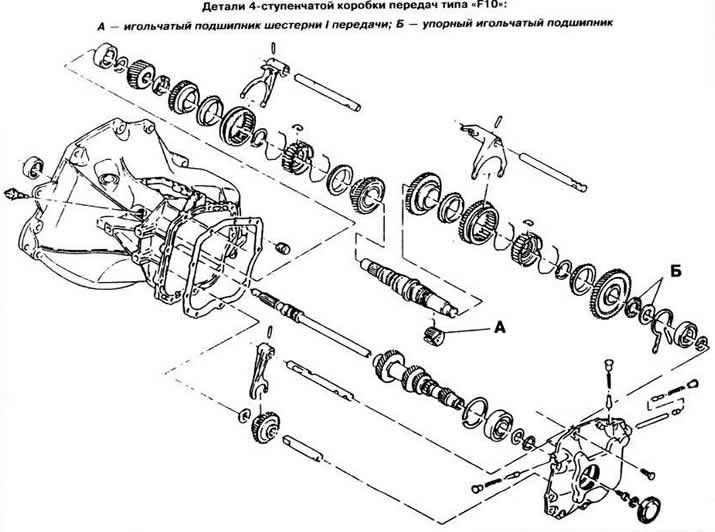
From April 1986 (. in the design of a 4- and 5-speed gearbox type «F10» the following changes have been made:
- the diameter of the blocking rings of the synchronizer of I and II gears has been increased from 51 to 58 mm. Accordingly, the design of the fork of the shift rod of I-II gears and the intermediate lever of the gear shift drive has been changed. Parts of the old and new designs are not interchangeable;
- all split ball bearings «open» type are replaced by sealed ball bearings, which can also be used for gearboxes manufactured before April 1986:
- in 4 speed gearbox «F10» 1st gear gear rotates on a split needle bearing «A» (see picture), and instead of the thrust washer of this gear, a thrust needle bearing is installed «B».
Vehicles with engine «16SV» fitted with a 4- or 5-speed gearbox «F13», which is a modification of the KP type «F10».
KP type «F13» has the same gear ratios as the gearbox type «F10*, except for the reverse gear ratio, and basically the same design, except for the following changes:
- reinforced crankcase;
- a synchronizer of I and II gears with three blocking rings is used;
- in a 4-speed gearbox, the 1st gear gear rotates on a split needle bearing. Instead of the thrust washer of the 1st gear gear, a thrust needle bearing is installed;
- the design of gears of I and II gears is adapted for a synchronizer with three blocking rings.
The composition of the synchronizer of I and II gears includes the following parts (see picture): gear 1 II gear; internal blocking rings 2; intermediate blocking rings 3; outer blocking rings 4; clutch 5; springs 6; crackers 7; hub 8 and gear 9 1st gear. After moving the clutch from the neutral position to the first gear position, the synchronizer works as follows: under the action of the springs, the three crackers are displaced by the clutch in the axial direction to the outer blocking ring. As a result, a gap is selected between the three blocking rings at their points of contact. Torque on the inner conical surface of the rings, arising from the difference in rotational speeds, causes the outer blocking ring to move until it touches the protrusions of the inner blocking ring, while the synchronizer sleeve is installed on the same axial line with the outer blocking ring. As soon as the clutch is further moved, it comes into contact with the outer blocking ring of the synchronizer. This process is called pre-sync.
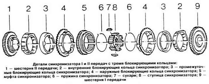
Under the action of force applied to the gear lever. which increases in accordance with the gear ratio of the gear shift mechanism, all three synchronizer rings are pressed against each other. As long as the speed difference between the gear and the clutch is maintained, the blocking rings are subjected to torques that are much greater than the torque generated in a conventional synchronizer, which provides a significant reduction in the effort required to shift gears. The method that allows you to completely align the speed of rotation of the synchronizer clutch and the corresponding gear is called basic synchronization.
- all split open type ball bearings have been replaced by sealed type bearings.
Marking
The transmission code number is stamped on the rear cover. For example 26412... 394, where:
- 264 is the ordinal number of the day of the year;
- 1 - the last digit of the year of issue;
- 2 - number of the shift that assembled the gearbox (1 - morning shift. 2 - evening shift);
- ... - a place for applying special codes from 0 to 99;
- 394 - gear ratio of the main gear. In this example, 3.94.
Gear ratios
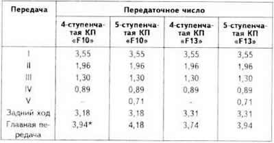
For vehicles with a body «sedan» And «hatchback» with engines «12SC», «13N» And «13S», for station wagons with these engines, the final drive ratio is 4.18, for vans with engines «13N» And «13S» — 4,53.
Differential
The differential box rotates on two tapered roller bearings. The bearing preload is adjusted with a nut.
The moment of resistance to rotation of the bearings of the differential box
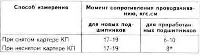
*Not counting torque measured during disassembly.
Visitor comments