


Removal
1. Open the hood.
Attention.
- Unless otherwise noted, the ignition switch must be in the OFF or LOCK position and all electrical equipment must be turned off before servicing any electrical components. The negative battery terminal must be disconnected to prevent sparking when touching exposed electrical terminals with tools or equipment. Failure to do so may result in personal injury and/or damage to the vehicle or its components.
- For owners of vehicles equipped with the OnStar system® (UE1) with backup battery:
- A backup battery is an alternative power source with some functional limitations in the event of a malfunction of the main battery. Do not disconnect the main battery or remove the OnStar® fuse when the ignition switch is in any position other than OFF. The temporary power supply function for accessories (RAP) must be deactivated in time or disabled (simply by opening the driver's door) before disconnecting power. Disconnecting power to the OnStar® module, either with the ignition on or with RAP enabled, may cause the OnStar® backup battery to activate, which may discharge or even damage the backup battery. If the backup battery is activated, it will remain connected until it is completely discharged. The backup battery is not rechargeable and must be replaced with a new one after use.
2. Turn off the ignition.
3. Disconnect the negative battery terminal.
4. Relieve pressure in the fuel system.
5. Raise and secure the vehicle.
6. Remove fuel from the tank.
7. Remove the exhaust pipe.
Caution: Do not blow through the fuel vapor recovery system lines or hoses. Fuel vapors inside the system components can cause poisoning.
8. Disconnect the quick-release connector (1) from the filler neck ventilation pipe (2).
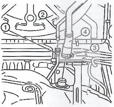
9. Remove the fuel tank filler hose fastening (3).
10. Remove the fuel tank filler hose (4).
11. Disconnect the quick-release connector from the front fuel vapor recovery system hose (1).
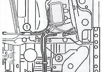
12. Disconnect the quick-release connector from the front fuel pressure line (2).
13. Place a suitable hydraulic jack under the fuel tank.
14. Loosen the mounting bolts (1) and remove the clamps (2) of the fuel tank.
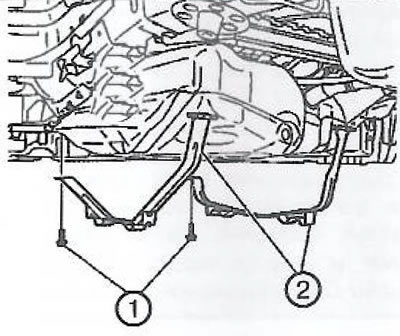
15. With the help of an assistant, lower the hydraulic jack to remove the fuel tank from the vehicle.
16. Disconnect the fuel pump wiring harness connector (1).
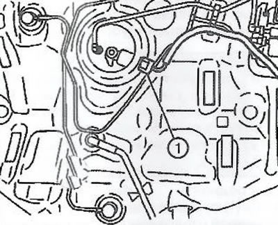
17. Remove the fuel tank from the hydraulic jack.
Disassembly
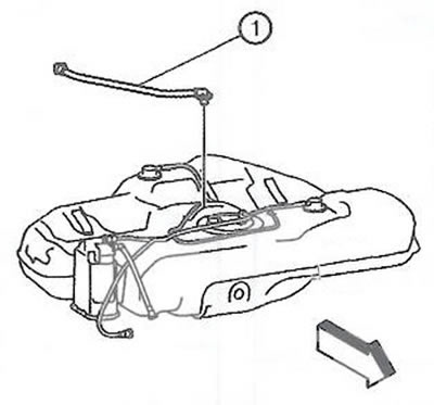
1. Remove the ventilation pipe (1) from the fuel tank.
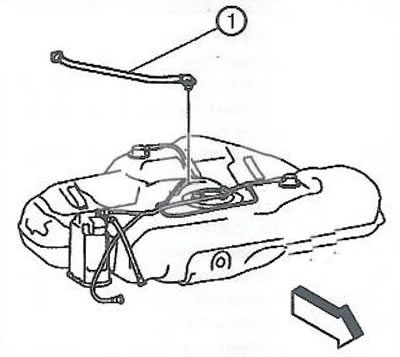
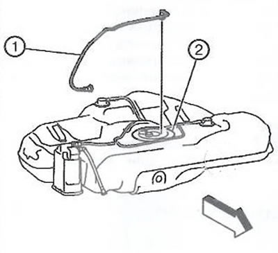
2. Disconnect the fuel pressure line (1) from the fuel tank and the fuel pump module (2).
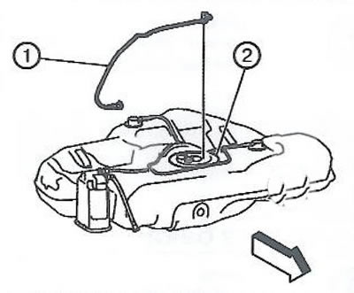
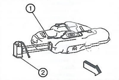
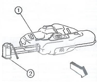
3. Disconnect the fuel tank vent pipe (1) from the charcoal filter (2) of the fuel vapor recovery system. Remove the charcoal filter (2) from the fuel tank.
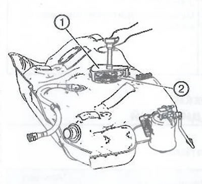
4. Install the EN-48279 tool (1) onto the fuel pump module retaining ring (2).
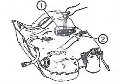
Note: Do not use a tool with a pulse drive. Considerable force is required to loosen the locking ring. Using a hammer and screwdriver is also not recommended. Fix the fuel tank to prevent the fuel tank from tipping over.
5. Using the EN-48279 tool and a long pry bar, turn the fuel pump module locking ring (1) counterclockwise to unlock the fuel pump module.
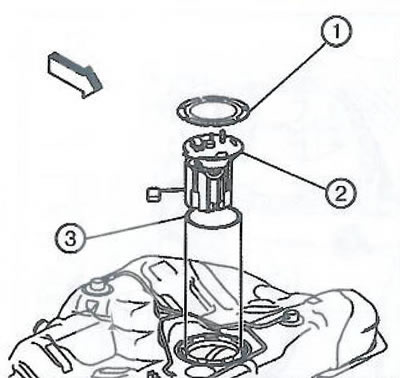
6. Remove the fuel pump module (2).
Note: Remove the fuel pump module from the tank slowly.
7. Remove and discard the fuel pump module sealing ring (3).
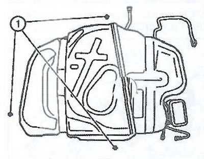
8. Loosen the fasteners (1) of the fuel tank protection.
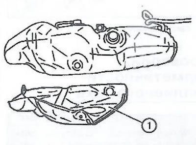
9. Remove the fuel tank protection (1).
Assembly
1. Install the fuel tank guard.
2. Install the fuel tank protection brackets.
3. Install a new fuel pump module sealing ring (3).
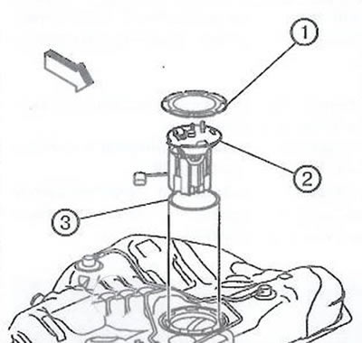
4. Install the fuel pump module (2) and retaining ring (1).
Note: Do not use a tool with a pulse drive. Considerable force is required to loosen the locking ring. Using a hammer and screwdriver is also not recommended. Fix the fuel tank to prevent the fuel tank from tipping over.
5. Using the EN-48279 tool and a long pry bar, turn the fuel pump module locking ring (1) clockwise to lock the fuel pump module.
6. Connect the ventilation pipe (1) of the fuel tank to the charcoal filter of the fuel vapor recovery system (2), then install the charcoal filter on the fuel tank.
7. Connect the fuel pressure line (1) to the fuel tank and the fuel pump module (2).
8. Install the ventilation pipe (1) of the filler neck onto the fuel tank.
Installation
1. Install the fuel tank on a hydraulic jack.
2. Connect the fuel pump module wiring harness connector (1).
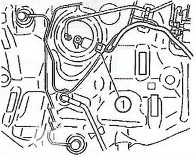
3. With the help of an assistant, install the fuel tank on the vehicle.
4. Install the fuel tank clamps (2) and tighten the mounting bolts (1).
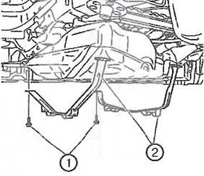
5. Remove the hydraulic jack from under the fuel tank.
6. Connect the front fuel pressure line quick-release connector (2).
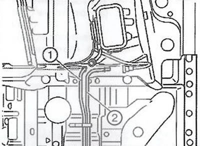
7. Connect the quick-release connector (1) of the front fuel vapor recovery system pipe.
8. Install the filling hose (4) onto the fuel tank.
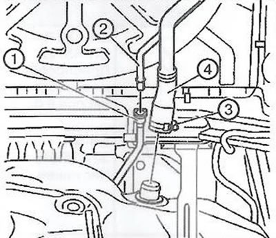
9. Install the clamp (3) on the filling hose and tighten to a torque of 4 Nm.
10. Connect the quick-release connector (1) of the fuel tank filler neck ventilation pipe.
11. Install the exhaust system.
12. Connect the negative battery terminal.
13. Close the hood.
Visitor comments