


Open large image in new tab →
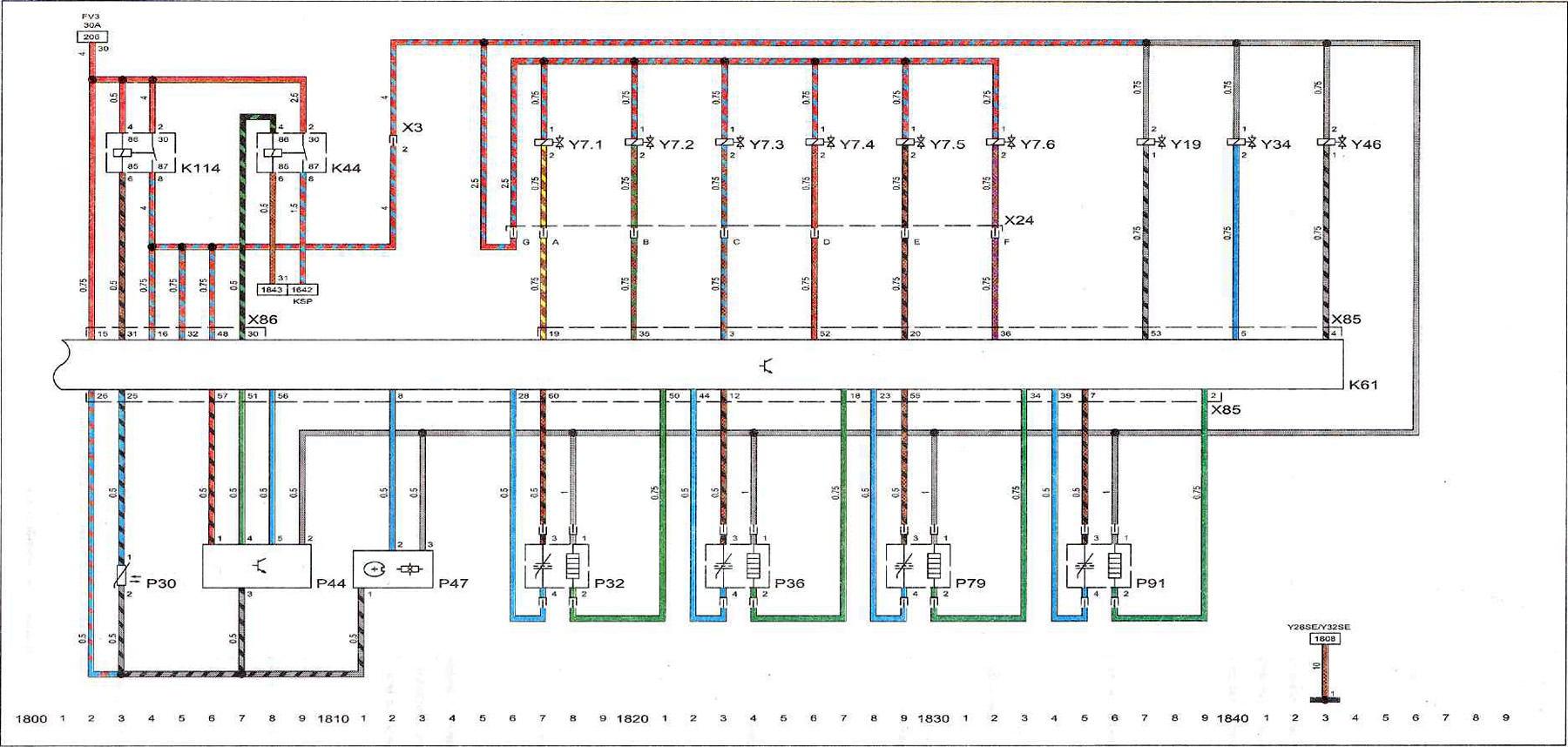
Key to diagram 6
| K44 | fuel pump relay |
| K61 | engine control unit with fuel injection system Motronic |
| K114 | main relay |
| P30 | coolant temperature sensor |
| R32 | heated lambda probe |
| R36 | heated lambda probe |
| R44 | mass air flow sensor |
| R47 | camshaft position sensor |
| R79 | lambda probe, catalyst |
| R91 | lambda probe, catalyst |
| Y7.1 | injector cylinder #1 |
| X1.2 | injector cylinder #2 |
| Y7.3 | n23 cylinder injector |
| Y7.4 | n24 cylinder injector |
| Y7.5 | n25 cylinder injector |
| Y7.6 | n26 cylinder injector |
| Y19 | valve on the intake manifold |
| Y34 | fuel tank ventilation valve |
| Y46 | valve on the intake manifold |
| I don't know | engine wiring harness plug on instrument panel |
| X24 | injector plug |
| X85 | engine wiring harness plug and Motronic injection system control unit |
| X86 | motronic injection system control unit wiring harness plug on the instrument panel |
| I | ground point (-) on the front left side |
| 30 | permanently energized terminal |
| 30A | 30 Amps |
| FV3 | main fuse FV3 |
| KSP | fuel pump |
| 31 | point of "mass" (-) |
Visitor comments