


Open large image in new tab →
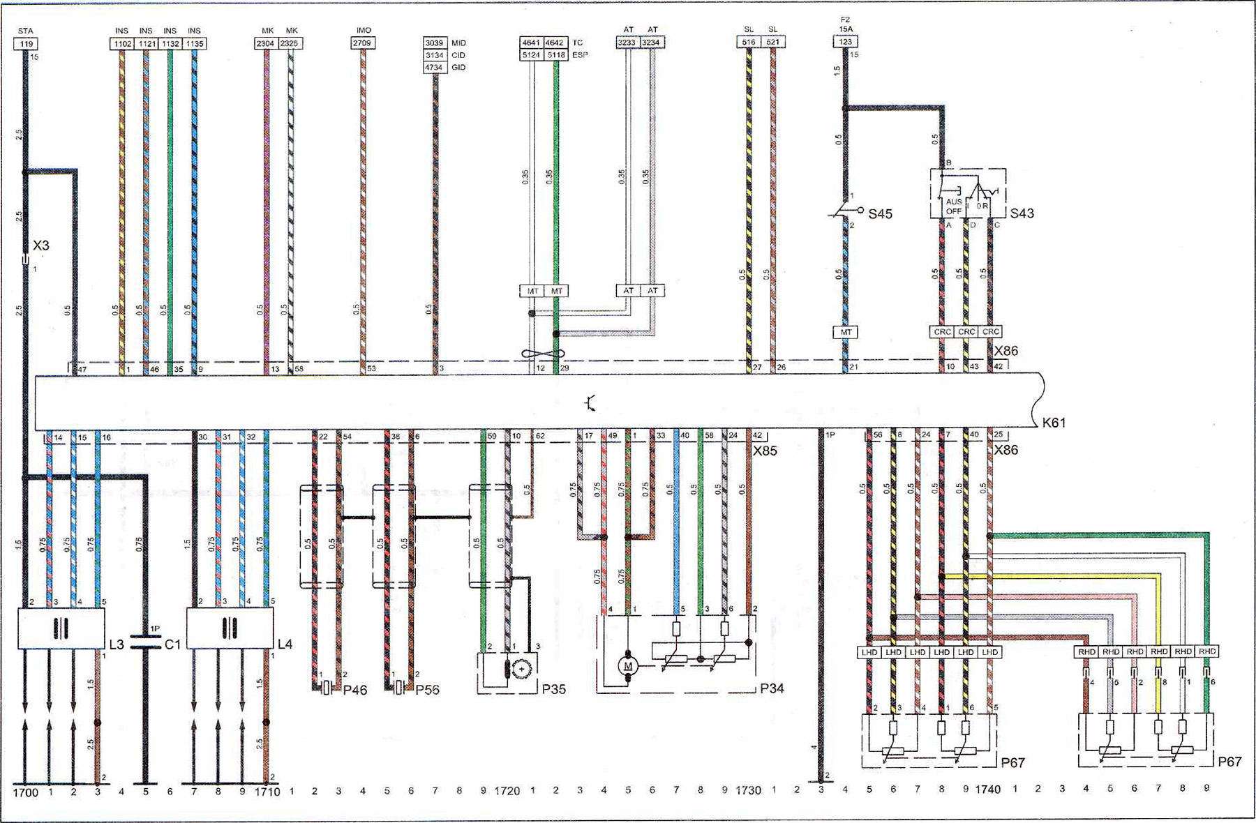
Key to diagram 7
| C1 | ignition coil |
| K61 | engine control unit with Motronic injection system |
| L3 | ignition coil. Cylinders 1,3,5 |
| L4 | ignition coil. Cylinders 2,4,6 |
| R34 | throttle position potentiometer |
| R35 | crankshaft position sensor |
| R46 | knock sensor 1 |
| R56 | knock sensor 2 |
| R67 | accelerator pedal position potentiometer |
| S43 | cruise control switch |
| S45 | clutch pedal switch, cruise control switch |
| X3 | engine wiring harness plug on instrument panel |
| X85 | engine wiring harness plug and Motronic injection system control unit |
| X86 | motronic injection system control unit wiring harness plug on the instrument panel |
| 2 | ground point (-) on the engine |
| 15 | ignition voltage supply terminal |
| 15A | 15 Amps |
| AT | automatic transmission |
| CID | color information display |
| CRC | cruise control |
| ESP | stability control system |
| INS | instrument panel |
| LHD | left hand drive cars |
| MID | multifunctional display |
| MK | engine cooling system |
| MT | manual transmission |
| RHD | right hand drive cars |
| F2 | fuse F2 |
| GID | graphic information display |
| IMO | immobilizer (anti-theft system) |
| SL | brake lights |
| STA | starter and battery charging |
| TC | traction control system |
(Original posted on the website: «opelbook»)
Visitor comments