


Open large image in new tab →
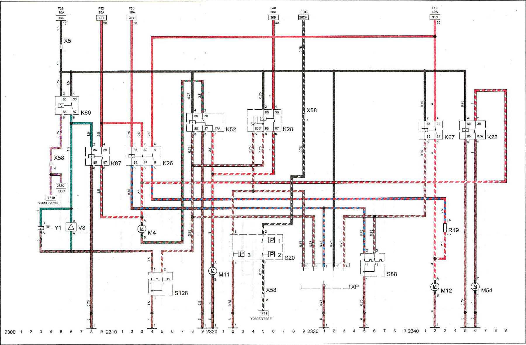
Key to diagram 10
| K22 | water pump relay |
| K26 | radiator fan relay |
| K28 | radiator fan relay |
| K52 | radiator fan relay |
| K60 | air conditioner compressor relay |
| K67 | radiator fan relay |
| K87 | radiator fan relay |
| M4 | radiator fan electric motor |
| M11 | radiator fan electric motor |
| M12 | radiator fan electric motor |
| M54 | water pump |
| R19 | additional resistance of the cabin air blower |
| S20 | cabin air blower switch |
| S20.1 | cabin air blower switch. Low speed rotation |
| S20.2 | cabin air blower switch. High speed rotation |
| S20.3 | cabin air blower switch. High speed rotation |
| S88 | coolant temperature sensor |
| S128 | coolant temperature sensor |
| V8 | cabin air blower diode |
| Y1 | electromagnetic clutch of air conditioner compressor |
| X5 | cooling system wiring harness plug on instrument cluster |
| X58 | cooling system wiring harness plug on the instrument panel |
| XP | diagnostic connector. Radiator fan contact |
| I | ground point (-) on the front left side |
| 10A | 10 Amps |
| 15 | ignition voltage supply terminal |
| 30 | permanently energized terminal |
| 30A | 30 Amps |
| 40A | 40 Amps |
| ESS | air conditioner with automatic climate control |
| F29 | fuse F29 |
| F40 | fuse F40 |
| F42 | fuse F42 |
| F50 | fuse F50 |
| F52 | fuse F52 |
Visitor comments