
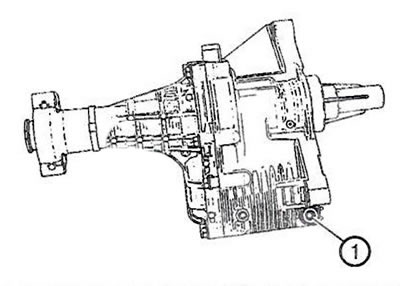
drain plug (1) The Graziano-PTU transfer box is located at the front of the crankcase.
The primary function of a transfer case is to transfer power from the gearbox via hypoid gears to the differential clutch via the propeller shaft. The intermediate shaft passes through the transfer case to the right front wheel of the vehicle.
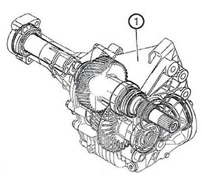
Transfer case (1) completely mechanical. It serves to transmit torque to the rear wheels of the car. The transfer case basically consists of four shafts needed to transmit torque. One shaft transmits torque to the front right wheel, it is called the intermediate drive shaft. The input shaft transmits torque to the secondary shaft, which transmits torque, changing its direction, to the pinion shaft. The gears of the transfer case operate in hypoid gear oil, and the shafts are sealed in the crankcase with oil seals.
Transfer case (1) completely mechanical. It serves to transmit torque to the rear wheels of the car. The transfer case basically consists of four shafts needed to transmit torque. One shaft transmits torque to the front right wheel, it is called the intermediate drive shaft. The input shaft transmits torque to the secondary shaft, which transmits torque, changing its direction, to the pinion shaft. The gears of the transfer case operate in hypoid gear oil, and the shafts are sealed in the crankcase with oil seals.
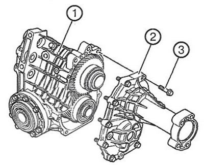
The crankcase and rear extension of the transfer case are made of die-cast aluminum alloy. For strengthening the crankcase and transfer case cover (1) Numerous stiffening ribs are used, which also serve to cool the unit. Rear extension (2) transfer box is attached to the crankcase with nine bolts (3), and the correct installation is ensured by two dowel pins. The contact surfaces between the crankcase and the rear extension of the transfer case are sealed with sealant.
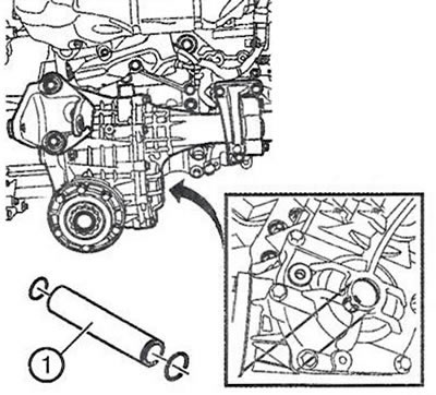
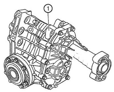
The transfer case housing is attached to the gearbox by four bolts, each of which is accessed through an idle gear whose shaft runs inside the ring gear shaft. locating pin (1) on the crankcase of the transfer case ensures the correct relative position of the transfer case and gearbox. The connection between the transfer case housing and the gearbox is sealed with an O-ring. Two opposed radial cuffs seal the input shaft, and between the cuffs in the transfer case housing there is an overflow hole.
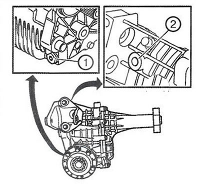
Air vent (2) located at the top of the transfer case housing, and the magnetic drain plug (2) installed at the bottom. The transfer box housing is also equipped with mounting points for mounting the rear of the unit. The rear mounting bracket is attached to the crankcase with three bolts. Inside, the transfer case housing has bearings for the input shaft, as well as the ring gear shaft. The bearings are adjusted with special gaskets installed behind the bearings.
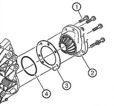
Flange (2) the rear output shaft is attached to the transfer case housing with seven bolts (1) and has an O-ring (4). Pad (3) serves to adjust the position of the rear output shaft gear on the ring gear.
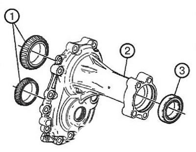
Input shaft bearings (1) in extension cord (2) transfer case serve as supports for the input shaft and ring gear shaft, and the bearing (3) supports the intermediate drive shaft of the right front wheel of the car.
The rear extension of the transfer case has a neck through which the intermediate shaft of the right front wheel passes. The neck partly serves as a holder for the countershaft bearing, and partly as the attachment point for the transfer case to the engine. The support bearing of the intermediate shaft is in-line ball bearing, sealed, pre-lubricated. It is fixed in the rear extension of the transfer case with a retaining ring.
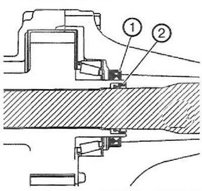
Radial cuff (1) mounted in the rear extension of the transfer case on the input shaft so that the oil cannot escape from the neck of the transfer case extension. A radial cuff is installed inside the input shaft (2), which performs the same function.
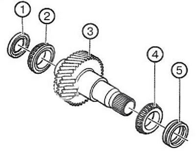
input shaft (3) needed to transfer power from the transfer case. There are splines on one end of the input shaft that fit into the transmission differential case, so the rotation speed of the input shaft is the same as that of the transmission ring gear. Two opposed radial cuffs installed in the transfer case crankcase (5) designed to seal the input shaft. The other end of the input shaft is equipped with an internal radial collar sealing the intermediate drive shaft passing inside the input shaft. Outside, the shaft is sealed with a radial seal (1).
The oblique arrangement of the teeth of the input shaft gear reduces the operating noise and increases the meshing area of the teeth. The gear engages with the ring gear of the transfer case.
The input shaft is mounted in two tapered roller bearings (2, 4). The bearings are adjusted with shims installed between the bearings and the transfer case housing.
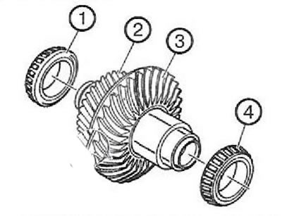
The ring gear shaft is located under the input shaft and is driven from its gear. This shaft has a relatively large diameter and is empty inside. The shaft has a helical gear (2) and ring gear (3). The helical gear engages the input shaft and the ring gear drives the rear output shaft flange.
The ring gear shaft is mounted in two tapered roller bearings (1, 4). The bearings are adjusted with shims installed between the bearings and the transfer case housing.
The rear output shaft flange, combined with the flange gear in one piece, is mounted with two tapered roller bearings mounted opposite each other. The bearings compensate for the axial force acting on the rear output shaft.
The flange of the rear output shaft is hollow and has internal splines into which the front propeller shaft rod is inserted, equipped with a spring ring to fix the rod inside the flange.
Visitor comments